StellarF4 Flight Controller
StellarF4 is an autopilot by Stingbee.
Features
- Processor
STM32F405
- Sensors
ICM-42688p/BMI270 Acc/Gyro
DPS310/BMP280 barometer
AT7456E OSD
W25Q128 dataflash
- Power
2S-6S Lipo input voltage with voltage monitoring
12V, 3A BEC for powering Video Transmitter
5V, 2A BEC for internal and peripherals
- Interfaces
10x PWM outputs DShot capable, PWM1-4 DShot capable
6x UARTs
1x I2C
2x ADC
SPI flash for logging
USB-C port
- LED
Red, 3.3V power indicator
Green, FC status
- Size
41 x 41mm PCB with 30.5mm M3 mounting
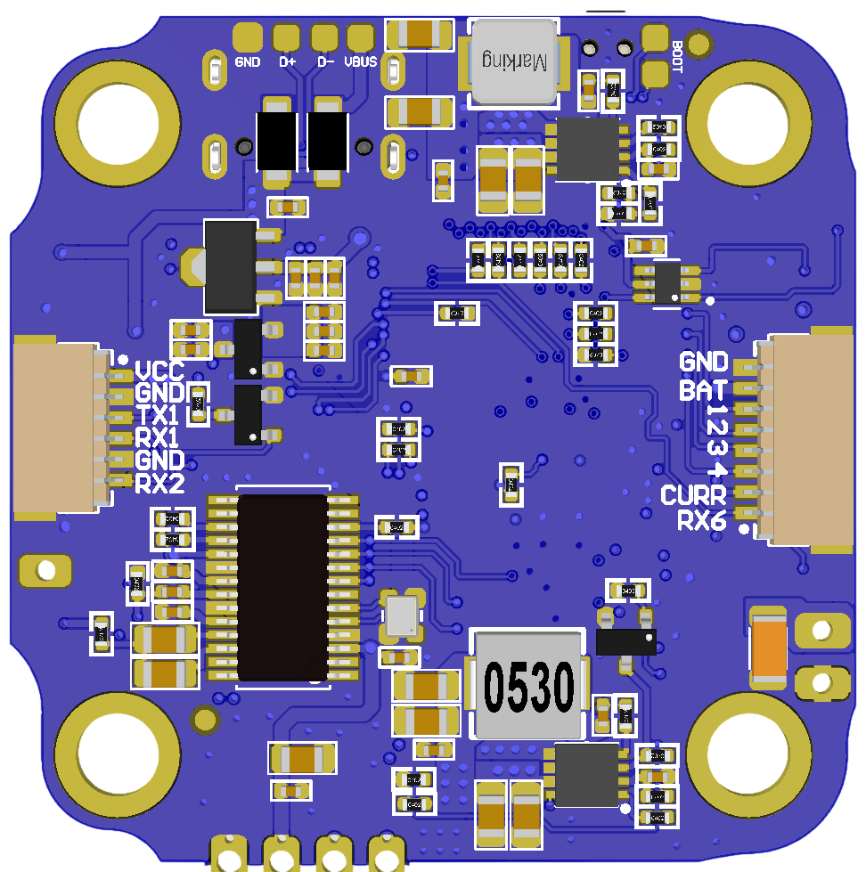
Pinout
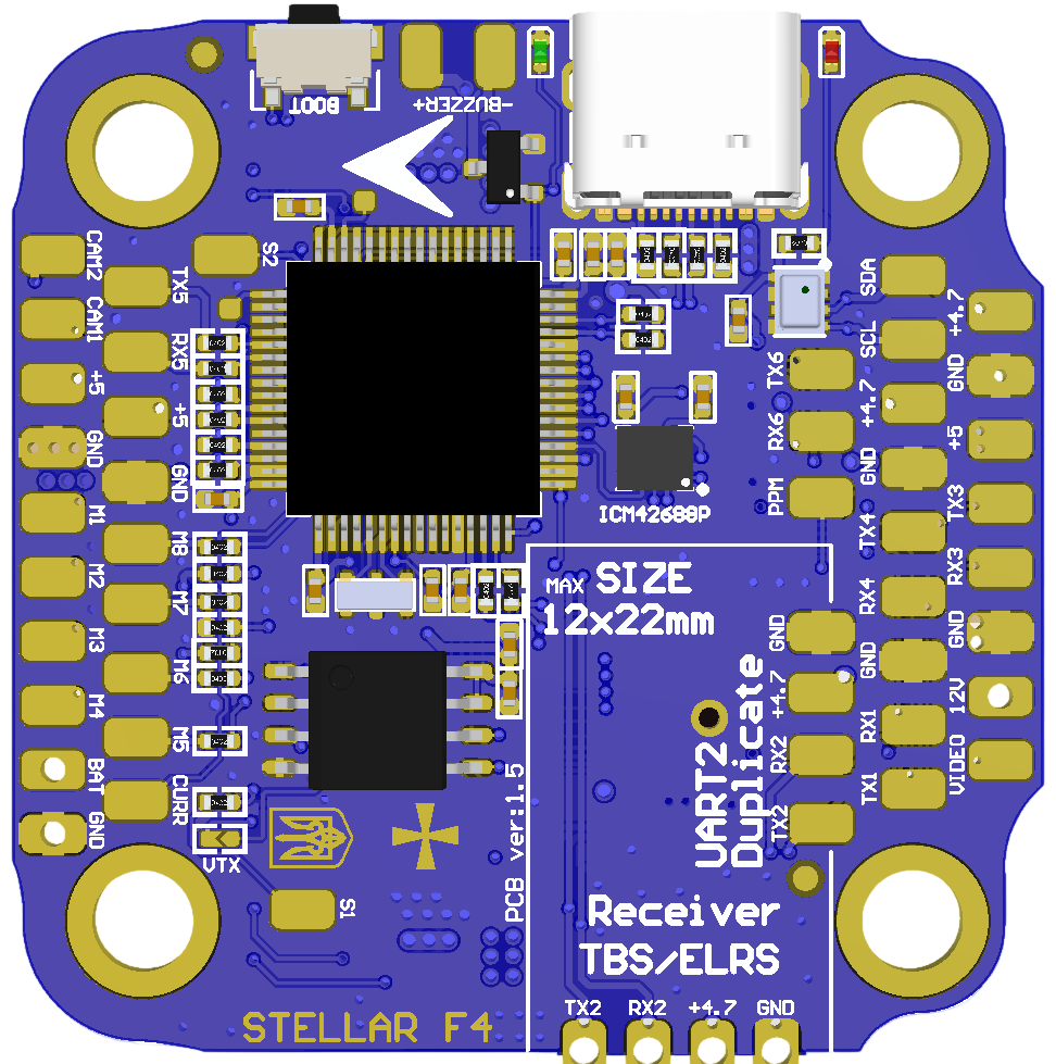
UART Mapping
The UARTs are marked RXn and TXn in the above pinouts. The RXn pin is the receive pin for UARTn. The TXn pin is the transmit pin for UARTn.
SERIAL0 -> USB
SERIAL1 -> USART1 (DJI / VTX, DMA capable)
SERIAL2 -> USART2 (Serial RC input, DMA capable)
SERIAL3 -> USART3 (User) (NO DMA)
SERIAL4 -> UART4 (User) (NO DMA)
SERIAL5 -> UART5 (ESC Telemetry) (NO DMA)
SERIAL6 -> USART6 (GPS) (NO DMA)
RC Input
The default RC input is configured on the UART2(SERIAL1) RX2 input and can be used for all ArduPilot supported unidirectional receiver protocols except PPM.
SBUS/DSM/SRXL connects to the RX2 pin.
CRSF also requires a TX2 connection, in addition to RX2, and automatically provides telemetry.
FPort requires connection to TX2 and SERIAL1_OPTIONS set to “7”. See FPort Receivers.
SRXL2 requires a connection to TX2 and automatically provides telemetry. Set SERIAL1_OPTIONS to “4”.
OSD Support
StellarF4 supports using its internal OSD using OSD_TYPE 1 (MAX7456 driver). External OSD support such as DJI or DisplayPort can be used simultaneously and is preconfigured on SERIAL3 but can be supported on any spare UART. See MSP OSD for more info.
PWM Output
StellarF4 supports up to 10 PWM/Dshot outputs. PWM1-4 outputs support Bi-Directional DShot.
Channels 1-4 support bi-directional DShot. Channels 1-8 marked as M1-M8 on the board. Channels 9-10 marked as S1-S2 on the board. PWM outputs are grouped and every group must use the same output protocol:
1, 2, 3, 4 are Group 1;
5, 6, 7, 8 are Group 2;
9 is Group 3;
10 is Group 4;
Battery Monitoring
The board has 1 built-in voltage divider on an ADC input and 1x current ADC input and supports an external 3.3V based current sensor. The voltage input is compatible with 2~6S LiPo batteries.
The default battery parameters are:
BATT_MONITOR = 4
BATT_VOLT_PIN = 10
BATT_CURR_PIN = 11 (CURR pin)
BATT_VOLT_MULT = 11
BATT_AMP_PERVLT = 52.7
Compass
StellarF4 does not have a built-in compass, but you can attach an external compass using I2C on the SDA and SCL pads.
Camera Switch
GPIO 81 controls which camera input (CAM1 or CAM2) is applied to the internal OSD. A RELAY function can be enabled to control the switching.
Loading Firmware
Firmware for these boards can be found at https://firmware.ardupilot.org in sub-folders labeled StellarF4.
Initial firmware load can be done with DFU by plugging in USB with the boot button pressed. Then you should load the “ardu*_with_bl.hex” firmware, using your favourite DFU loading tool. eg STM32CubeProgrammer
Subsequently, you can update firmware with Mission Planner.