SequreH743
The SequreH743 and SequreH743v2 are flight controllers designed and produced by Sequre.
Features
MCU - STM32H743xx 32-bit processor running at 480 MHz
IMU - MPU6000, ICM42688 (V2 version)
Barometer - BMP280 (DPS368 and DPS310 on V2)
OSD - AT7456E
6x UARTs
9x PWM Outputs (8 Motor Output, 1 LED)
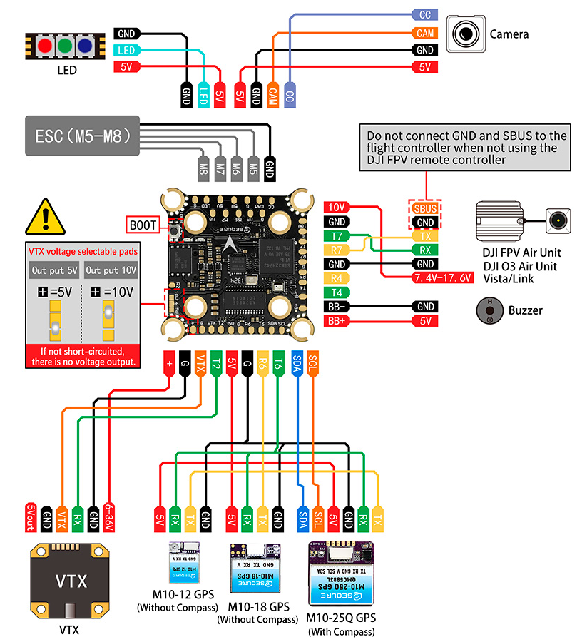
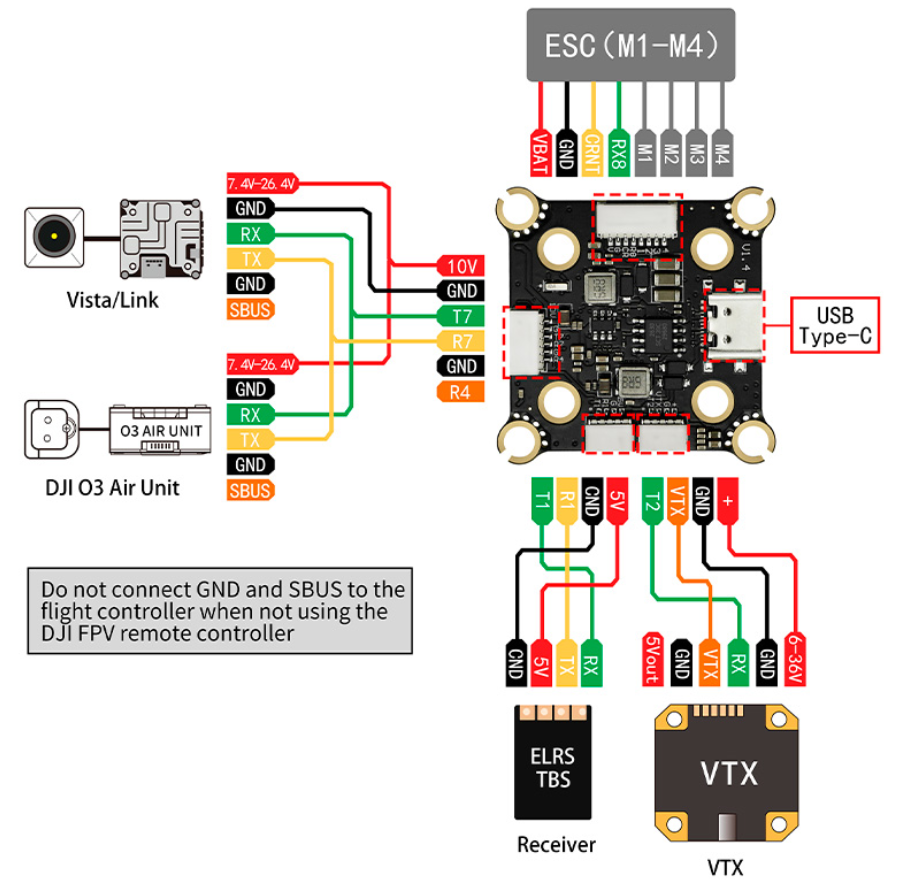
Pinout
UART Mapping
The UARTs are marked Rn and Tn in the above pinouts. The Rn pin is the receive pin for UARTn. The Tn pin is the transmit pin for UARTn.
SERIAL0 -> USB (MAVLink2)
SERIAL1 -> USART1 (RCIN, DMA-enabled)
SERIAL2 -> USART2 (SmartAudio)
SERIAL4 -> UART4 (None)
SERIAL6 -> USART6 (GPS, DMA-enabled)
SERIAL7 -> UART7 (DisplayPort, DMA-enabled)
SERIAL8 -> UART8 (ESCTelemetry)
RC Input
The default RC input is configured on USART1. RC could be applied instead to a different UART port such as and set the protocol to receive RC data SERIALn_PROTOCOL = 23 and change SERIAL1 _PROTOCOL to something other than ‘23’. For RC protocols other than unidirectional, the USART1_TX pin will need to be used:
FPort would require SERIAL1_OPTIONS be set to “15”.
CRSF would require SERIAL1_OPTIONS be set to “0”.
SRXL2 would require SERIAL1_OPTIONS be set to “4” and connects only the TX pin.
PPM is not supported
OSD Support
The SequreH743 supports OSD using its MAX7456by default, and simultaneously DisplayPort using UART7 on the HD VTX connector if OSD_TYPE2 is set to “5”.
VTX Support
The SH1.0-6P connector supports a DJI Air Unit / HD VTX connection. Protocol defaults to DisplayPort. Pin 1 of the connector is 9v so be careful not to connect this to a peripheral that can not tolerate this voltage.
Camera control
GPIO 81 is a pin for PWM camera control (CC pad) which is not supported by ArduPilot. It can be used as a general GPIO pin. By default RELAY2 is configured to control this pin and sets the GPIO high.
PWM Output
The SequreH743 supports up to 9 PWM or DShot outputs. The pads for motor output M1 to M9 are provided on both the motor connectors and on separate pads, plus separate pad for LED strip (default configuration) or another PWM output.
The PWM is in 4 groups:
PWM 1-4 in group1
PWM 5-6 in group2
PWM 7-8 in group3
PWM 9 (LED) in group4
Channels within the same group need to use the same output rate. If any channel in a group uses DShot then all channels in the group need to use DShot. Channels 1-8 support bi-directional dshot.
Battery Monitoring
The board has a internal voltage sensor and connections on the ESC connector for an external current sensor input. The voltage sensor can handle up to 6S LiPo batteries.
The default battery parameters are: * BATT_MONITOR = 4 * BATT_VOLT_PIN = 13 * BATT_CURR_PIN = 12 (CURR pin) * BATT_VOLT_MULT = 11.0 * BATT_AMP_PERVLT = 17.2
Compass
The SequreH743 does not have a built-in compass, but you can attach an external compass using I2C on the SDA and SCL pads.
Loading Firmware
Firmware for these boards can be found here in sub-folders labeled “SequreH743”.
Initial firmware load can be done with DFU by plugging in USB with the bootloader button pressed. Then you should load the “with_bl.hex” firmware, using your favourite DFU loading tool.
Once the initial firmware is loaded you can update the firmware using any ArduPilot ground station software. Updates should be done with the *.apj firmware files.