Holybro Kakute H7 V1
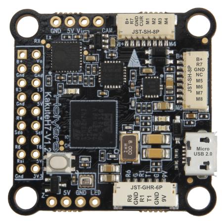
above image and some content courtesy of Holybro
Where to Buy
Available from many retailers including Holybro
Specifications
Processor
STM32H743 32-bit processor
Sensors
InvenSense MPU6000 IMU (accel and gyro only, no compass)
BMP280 barometer
Power
2S - 6S Lipo input voltage with voltage monitoring
9V, 1.5A BEC for powering Video Transmitter
Interfaces
9x PWM outputs (9th pwm output is for NeoPixel LED string via the LED pad)
1x RC input
6x UARTs/serial for GPS and other peripherals
1x I2C port for external compass
micro USB port
All UARTS support hardware inversion. SBUS, SmartPort, and other inverted protocols work on any UART without “uninvert hack”
microSD Card Slot for logging
AT7456E OSD
External current monitor input
Pinout
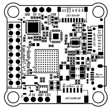
UART Mapping
The UARTs are marked Rn and Tn in the above pinouts. The Rn pin is the receive pin for UARTn. The Tn pin is the transmit pin for UARTn.
SERIAL0 -> USB
SERIAL1 -> UART1 (Telem1)
SERIAL2 -> not available externally
SERIAL3 -> UART3 (GPS)
SERIAL4 -> UART4
SERIAL5 -> not available
SERIAL6 -> UART6 (UART6 RX normally RCinput unless BRD_ALT_CONFIG = 1)
SERIAL7 -> UART7 (RX7 only available, normally used for ESC telemetry)
The SERIAL7 port (UART7) is normally for ESC telemetry, and has an R7 pin on both of the ESC connectors.
RC Input
The R6 pin, which by default is mapped to a timer input, can be used for all ArduPilot supported receiver protocols, except CRSF/ELRS and SRXL2 which require a true UART connection. However, FPort, when connected in this manner, will only provide RC without telemetry.
To allow CRSF and embedded telemetry available in Fport, CRSF, and SRXL2 receivers, the R6 pin can also be configured to be used as true UART RX pin for use with bi-directional systems by setting the BRD_ALT_CONFIG to “1” so it becomes the SERIAL6 port’s RX input pin.
With this option, SERIAL6_PROTOCOL must be set to “23”, and:
PPM is not supported.
SBUS/DSM/SRXL connects to the R6 pin, but SBUS requires that the SERIAL6_OPTIONS be set to “3”.
FPort requires connection to T6 and SERIAL6_OPTIONS be set to “7”.
CRSF also requires a T6 connection, in addition to R6, and automatically provides telemetry. Set SERIAL6_OPTIONS to “0”.
SRXL2 requires a connection to T6 and automatically provides telemetry. Set SERIAL6_OPTIONS to “4”.
Any UART can be used for RC system connections in ArduPilot also, and is compatible with all protocols except PPM. See Radio Control Systems for details.
FrSky Telemetry
FrSky Telemetry is supported using the Tx pin of any UART including SERIAL6/UART6 . You need to set the following parameters to enable support for FrSky S.PORT (example shows SERIAL6). Note this assumes the RC input is using default (BRD_ALT_CONFIG = 0). Obviously, if using BRD_ALT_CONFIG = 1 for full duplex RC prtocols, you must a different UART for FrSky Telemetry.
OSD Support
The KakuteH7 supports OSD using OSD_TYPE 1 (MAX7456 driver).
PWM Output
The KakuteH7 supports up to 8 PWM outputs. Outputs are available via two JST-SH connectors. All 8 outputs support DShot as well as all PWM types.
The PWM is in 3 groups:
PWM 1, 2 in group1
PWM 3, 4 in group2
PWM 5, 6 in group3
PWM 7, 8 in group4
Channels within the same group need to use the same output rate, whether PWM or Dshot. If any channel in a group uses DShot then all channels in the group need to use DShot.
Note
for users migrating from BetaflightX quads, the first four outputs M1-M4 have been configured for use with existing motor wiring using these default parameters:
FRAME_CLASS = 1 (Quad)
FRAME_TYPE = 12 (BetaFlightX)
LED Output
The LED output is configured by default to support NeoPixel LED strings.
Battery Monitoring
The board has a built-in voltage sensor via the B+ pin, but no internal current sensor. An external current sensor can be connected to the CUR pin. Default parameters for both internal voltage and external current monitoring are set by default to the below for use with any Holybro Tekko32 F4 4in1 ESC.
The correct battery setting parameters are:
BATT_AMP_PERVLT 59.5
Compass
The KakuteH7 does not have a built-in compass, however you can attach an external compass using I2C on the SDA and SCL pads.
Firmware
Firmware for this board can be found here in sub-folders labeled “KakuteH7”.
Loading Firmware
Initial firmware load can be done with DFU by plugging in USB with the bootloader button pressed. Then you should load the “with_bl.hex” firmware, using your favourite DFU loading tool.
Once the initial firmware is loaded you can update the firmware using any ArduPilot ground station software. Later updates should be done with the *.apj firmware files.