NarinFC-H7/H5
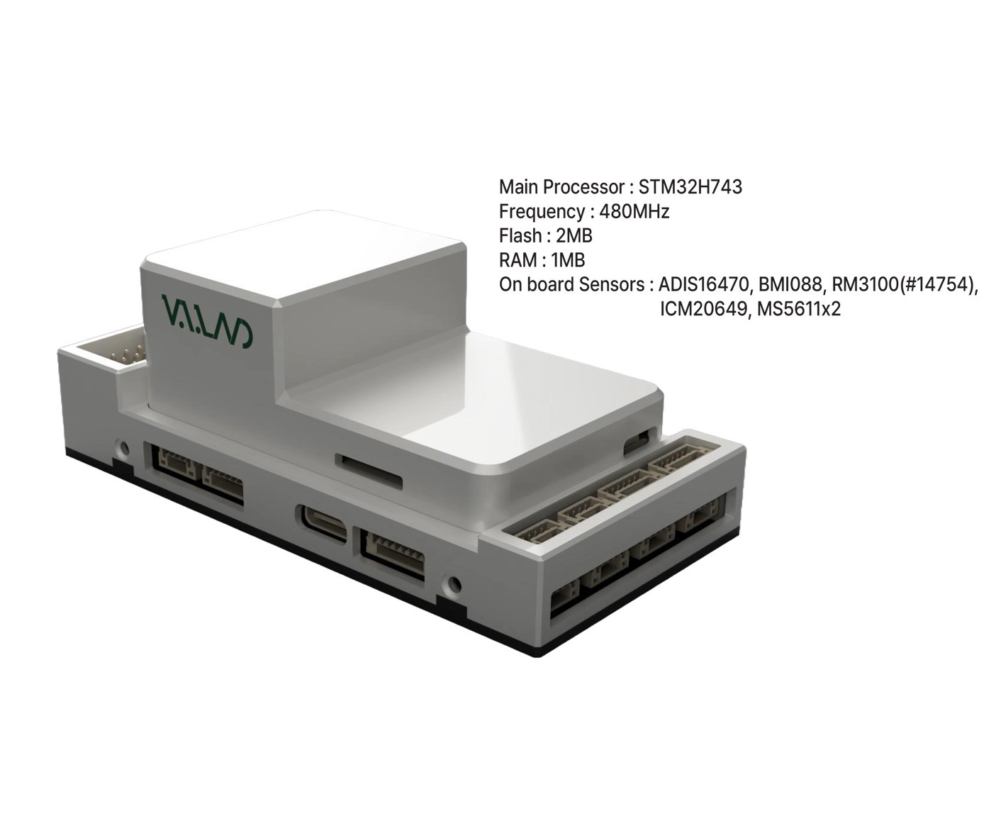
The NarinFC-H7/H5 is an advanced autopilot family designed in-house by VOLOLAND CO., LTD. It uses a high performance STM32H7 processor and integrates industrial-grade sensors.
Features/Specifications
- Processor
STM32H743
- Sensors
Accelerometer/Gyroscope: ADIS16470(H7) or ICM-45686(H5)
Accelerometer/Gyroscope: ICM-20649(H7 or ICM-45686(H5)
Accelerometer/Gyroscope: BMI088
Magnetometer: RM3100
Barometer: MS5611*2
- Interfaces
14 PWM servo outputs
Support multiple RC inputs (SBus / CPPM / DSM)
Analog/PWM RSSI input
2 GPS ports (GPS and UART4 ports)
4 ⅹ I2C buses
2 ⅹ CAN bus ports
2 ⅹ Power ports
2 ⅹ ADC ports
1 ⅹ USB-C port
- Power
Power 4.3V ~ 5.4V
USB Input 4.75V ~ 5.25V
- Size and Dimensions
93.4mm x 46.4mm x 34.1mm
106g
Where to Buy
Outline Dimensions

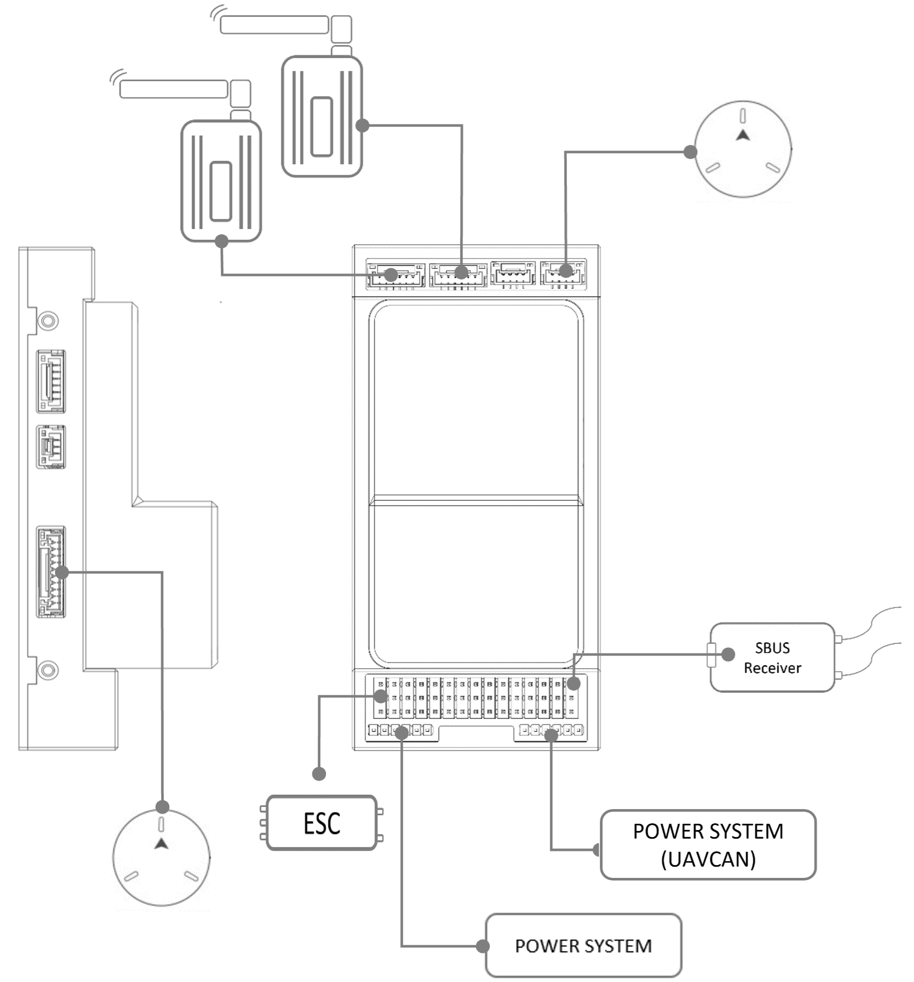
Wire Diagram
UART Mapping
SERIAL0 = USB (MAVLink2 default)
SERIAL1 = USART2,Telemetry1 (MAVlink2 default,DMA-enabled)
SERIAL2 = USART6,Telemetry2 (MAVlink2 default,DMA-enabled)
SERIAL3 = USART1,GPS1 (GPS default, DMA-enabled)
SERIAL4 = UART4,GPS2 (GPS2 default)
SERIAL5 = UART8 (not available except on custom carrier boards)(USER default,DMA-enabled)
SERIAL6 = UART7,DEBUG (USER)
SERIAL7 = USB2 (MAVLink2 default)
Serial protocols can be adjusted to personal preferences.
Connectors and Pinouts
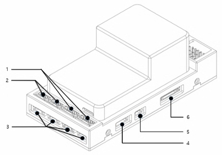
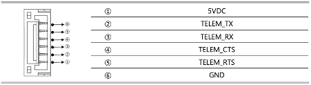
- 1. TELEM1, TELEM2 Port

JST GH 6P connector
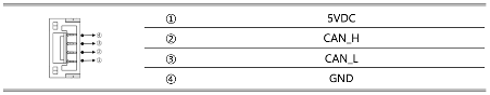
- 2. CAN1, CAN2 Port

JST GH 4P connector
- 3. I2C, I2C2, I2C3, I2C4 Port
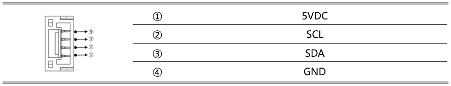
JST GH 4P connector
- 4. UART4 Port
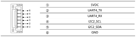
JST GH 6P connector
- 5. RSSI Port

RSSI input
- 6. GPS & Safety Port
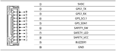
JST GH 10P connector
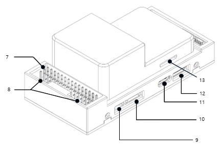
- 7. PWM & RC_IN
The NarinFC-H7 supports up to 14 PWM outputs. Outputs are grouped and all outputs within their group must be the same protocol.
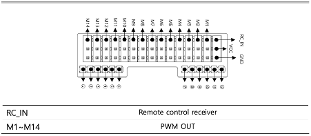
2.54mm pitch DuPont connector
RC_IN : Remote control receiver input for unidirectional protocols, others need to use a full UART
- 8. Power Input
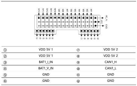
2mm pitch DuPont connector
- 9. ADC Port
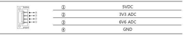
Spare ADC inputs
- 10. DEBUG & UART7 Port
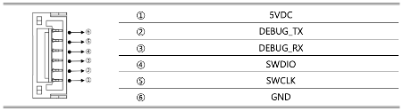
JST GH 6P connector
11. USB Port
USB C Type
- 12. SPI Port
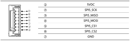
JST GH 7P connector
- 13. SD CARD
SD CARD


PWM Output
The NarinFC-H7 supports up to 14 PWM outputs. All outputs except M13 and M14 support DShot. Outputs 1-8 support Bi-Directional DShot.
The 14 PWM outputs are in 4 groups:
Outputs 1, 2, 3 and 4 in group1
Outputs 5, 6, 7 and 8 in group2
Outputs 9, 10, 11 and 12 in group3
Outputs 13 and 14 in group4
ALL outputs within the same group need to use the same output rate and protocol.
GPIOs
The 14 outputs can be used as GPIOs (relays, buttons, RPM etc). To use them you need to set the output’s SERVOx_FUNCTION to -1. See GPIOs for more information.
- The numbering of the GPIOs for use in the PIN parameters in ArduPilot is :
PWM1(M1) 50
PWM2(M2) 51
PWM3(M3) 52
PWM4(M4) 53
PWM5(M5) 54
PWM6(M6) 55
PWM7(M7) 56
PWM8(M8) 57
PWM9(M9) 58
PWM10(M10) 59
PWM11(M11) 60
PWM12(M12) 61
PWM13(M13) 62
PWM14(M14) 63
Analog inputs
The NarinFC-H7 has 2 analog inputs, one 6V tolerant and one 3.3V tolerant in addition to the power monitoring inputs and RSSI pin
ADC Pin16 -> BATT_VOLTAGE_SENS
ADC Pin17 -> BATT_CURRENT_SENS
ADC Pin14 -> BATT2_VOLTAGE_SENS
ADC Pin2 -> BATT2_VOLTAGE_SENS
ADC Pin4 -> SPARE1_ADC1(6.6V)
ADC Pin18 -> SPARE2_ADC1(3.3V)
ADC Pin6 -> RSSI_IN_ADC1(3.3V)
Battery Monitor
The board has two dedicated power monitor ports on 6 pin connectors, one for an analog monitor and one for a DroneCAN monitor. The correct battery setting parameters are dependent on the type of power brick which is connected. By default, use of a DroneCAN battery monitor is enabled by default as the first battery monitor.
RC Input
The RCIN pin, which by default is mapped to a timer input, can be used for all ArduPilot supported unidirectional receiver protocols. Bi-directional protocols such as CRSF/ELRS and SRXL2 require a full UART connection. FPort, when connected to RCIN, will only provide RC without telemetry.
To allow CRSF and embedded telemetry available in Fport, CRSF, and SRXL2 receivers, a full UART, such as SERIAL6 (UART7) would need to be used for receiver connections. Below are setups using Serial6.
SERIAL6_PROTOCOL should be set to “23”.
FPort would require SERIAL6_OPTIONS be set to “15”.
CRSF would require SERIAL6_OPTIONS be set to “0”.
SRXL2 would require SERIAL6_OPTIONS be set to “4” and connects only the TX pin.
Any UART can also be used for RC system connections in ArduPilot, and is compatible with all protocols except PPM. See Radio Control Systems for details. The power rail associated with this connector position is powered either via USB or PMU.
Loading Firmware
This board comes with ArduPilot firmware pre-installed and other vehicle/revision ArduPilot firmware can be loaded using most Ground Control Stations.
Firmware for these boards can be found here https://firmware.ardupilot.org in sub-folders labeled “NarinFC-H7”.
The board comes pre-installed with an ArduPilot bootloader, allowing the loading of *.apj firmware files with any ArduPilot compatible ground station, such as Mission Planner.