GreenSight UltraBlue
The UltraBlue flight controller is sold by GreenSight.
Features
STM32H743 microcontroller
Incorporates an NVIDIA Jetson SOM
Three IMUs: two BMI088 units and one ICM20649
Internal heater for IMU temperature control
DPS310 SPI barometer
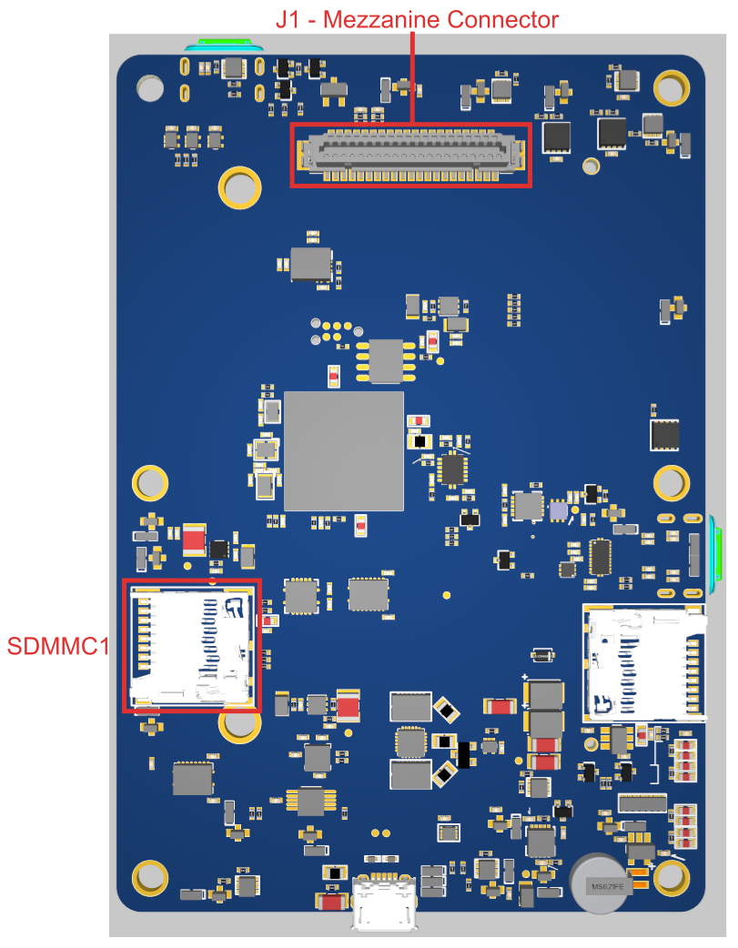
microSD card slot
DF9-41S-1V(32) Hirose Mezzanine Connector
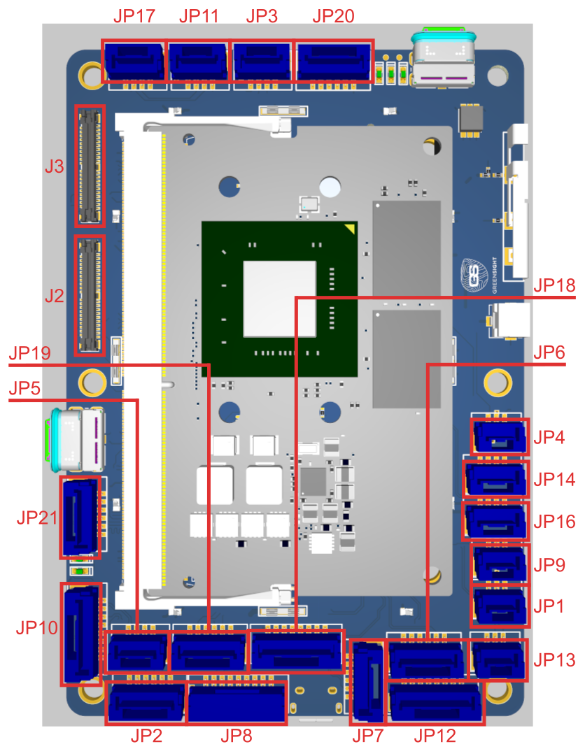
Connector Overview
UART Mapping
SERIAL0 -> USB (console)
SERIAL1 -> USART2 (Jetson telem, no DMA)
SERIAL2 -> USART6 (telem2)
SERIAL3 -> USART1 (primary GPS)
SERIAL4 -> UART4 (GPS2, no DMA)
SERIAL5 -> UART8 (USER/[RCin: DSM/PPM/SBus])
SERIAL6 -> USART3 (ESC telemetry)
SERIAL7 -> UART7 (USER/[debug tx/rx], no DMA)
SERIAL8 -> USB2
Connectors
All connectors are JST GH type unless otherwise specified.
JP1 - PPM/SBUS In (Autopilot RC input)
| Pin | Signal | Volt |
|---|---|---|
| 1 | PPM/SBUS | +3.3V |
| 2 | VCC | +5V |
| 3 | GND | GND |
JP9 - Analog (Autopilot ADC input)
| Pin | Signal | Volt |
|---|---|---|
| 1 | VCC | +5V |
| 2 | Autopilot Analog Input | Analog 0 to +6.6V |
| 3 | GND | GND |
JP16 - API2C4 (Autopilot I2C)
| Pin | Signal | Volt |
|---|---|---|
| 1 | VCC | +5V |
| 2 | Autopilot I2C Bus 4 Clock | +3.3V |
| 3 | Autopilot I2C Bus 4 Data | +3.3V |
| 4 | GND | GND |
JP14 - AP Debug (Autopilot debug UART)
| Pin | Signal | Volt |
|---|---|---|
| 1 | VCC | +5V |
| 2 | Autopilot Debug UART Transmit | +3.3V |
| 3 | Autopilot Debug UART Receive | +3.3V |
| 4 | GND | GND |
JP4 - Spektrum/DSM (Autopilot RC input)
| Pin | Signal | Volt |
|---|---|---|
| 1 | VCC | +3.3V |
| 2 | GND | GND |
| 3 | Spektrum/DSM | +3.3V |
JP18 - Autopilot SPI
| Pin | Signal | Volt |
|---|---|---|
| 1 | VCC | +5V |
| 2 | SPI5 Clock | +3.3V |
| 3 | SPI5 Master In Slave Out | +3.3V |
| 4 | SPI5 Master Out Slave In | +3.3V |
| 5 | SPI5 External Chip | +3.3V |
| 6 | SPI5 External Chip Select 2 | +3.3V |
| 7 | SPI5 External Chip Select 3 | +3.3V |
| 8 | GND | GND |
JP17 - Jetson Cooling Fan (Companion Computer)
| Pin | Signal | Volt |
|---|---|---|
| 1 | GND | GND |
| 2 | VCC | +5V |
| 3 | Jetson PWM Tach Input | +3.3V |
| 4 | Jetson PWM Fan Output | +3.3V |
JP3 - CAN 1 (Autopilot and Jetson Companion Computer)
Note
CAN 1 is connected to Jetson, Payloads and AP.
| Pin | Signal | Volt |
|---|---|---|
| 1 | VCC | +5V |
| 2 | Autopilot and Jetson CAN High | +3.3V |
| 3 | Autopilot and Jetson CAN Low | +3.3V |
| 4 | GND | GND |
JP11 - CAN 2 (Autopilot)
| Pin | Signal | Volt |
|---|---|---|
| 1 | VCC | +5V |
| 2 | Autopilot only CAN High | +3.3V |
| 3 | Autopilot only CAN Low | +3.3V |
| 4 | GND | GND |
JP10 - Ethernet (Companion Computer)
Note
JP10 is a capacitively coupled ethernet port due to space constraints. It officially supports 10/100 communication over 4x of the pins, MDI pairs 0 and 1, which would correspond to pins 1, 2, 3, and 6 on a standard RJ-45 end (Orange and Green ethernet cable/RJ-45 pairs). Even though these pairs are capacitively coupled, full Gigabit capability has been tested and verified in the lab with all 8x pins in use; the caveat is that this test was done with a cable ~1m long. Speeds above 10/100 may be unstable with longer cable lengths and are not guaranteed. Dual 10/100 connections may also be possible, though this is entirely dependent on the capabilities of the Jetson module itself.
| Pin | Signal | Volt |
|---|---|---|
| 1 | Jetson Ethernet (Cap Coupled) | +3.3V |
| 2 | Jetson Ethernet (Cap Coupled) | +3.3V |
| 3 | Jetson Ethernet (Cap Coupled) | +3.3V |
| 4 | Jetson Ethernet (Cap Coupled) | +3.3V |
| 5 | Jetson Ethernet (Cap Coupled) 10/100 | +3.3V |
| 6 | Jetson Ethernet (Cap Coupled) 10/100 | +3.3V |
| 7 | Jetson Ethernet (Cap Coupled) 10/100 | +3.3V |
| 8 | Jetson Ethernet (Cap Coupled) 10/100 | +3.3V |
JP13 - Jetson Debug (Companion Computer UART)
| Pin | Signal | Volt |
|---|---|---|
| 1 | Jetson UART Debug Transmit | +3.3V |
| 2 | Jetson UART Debug Receive | +3.3V |
| 3 | GND | GND |
JP2 - AP Telem 2 (Autopilot UART)
| Pin | Signal | Volt |
|---|---|---|
| 1 | VCC | +5V |
| 2 | Autopilot Telem 2 UART Transmit | +3.3V |
| 3 | Autopilot Telem 2 UART Receive | +3.3V |
| 4 | Autopilot Telem 2 UART Clear to Send | +3.3V |
| 5 | Autopilot Telem 2 UART Request to Send | +3.3V |
| 6 | GND | GND |
JP19 - JET_SER_1 (Companion Computer UART)
| Pin | Signal | Volt |
|---|---|---|
| 1 | VCC | +5V |
| 2 | Jetson UART 1 Transmit | +3.3V |
| 3 | Jetson UART 1 Receive | +3.3V |
| 4 | Jetson UART 1 Clear to Send | +3.3V |
| 5 | Jetson UART 1 Request to Send | +3.3V |
| 6 | GND | GND |
JP7 - GPS 2 (Autopilot UART/I2C)
| Pin | Signal | Volt |
|---|---|---|
| 1 | VCC | +5V |
| 2 | Autopilot GPS2 UART Transmit | +3.3V |
| 3 | Autopilot GPS2 UART Receive | +3.3V |
| 4 | Autopilot I2C Bus 2 Clock (GPS2 SCL) | +3.3V |
| 5 | Autopilot I2C Bus 2 Data (GPS2 SDA) | +3.3V |
| 6 | GND | GND |
JP5 - Jetson I2C (Companion Computer)
| Pin | Signal | Volt |
|---|---|---|
| 1 | GND | GND |
| 2 | Jetson I2C Bus 1 Clock | 3.3V |
| 3 | Jetson I2C Bus 1 Data | 3.3V |
| 4 | VCC | +5V |
JP6 - GPS 1 (Autopilot UART/I2C)
| Pin | Signal | Volt |
|---|---|---|
| 1 | VCC | +5V |
| 2 | Autopilot GPS1 UART Transmit | +3.3V |
| 3 | Autopilot GPS1 UART Receive | +3.3V |
| 4 | Autopilot I2C Bus 1 Clock (GPS1 SCL) | +3.3V |
| 5 | Autopilot I2C Bus 1 Data (GPS1 SDA) | +3.3V |
| 6 | GND | GND |
JP20 - JET_SPI (Companion Computer SPI)
| Pin | Signal | Volt |
|---|---|---|
| 1 | VCC | +5V |
| 2 | Jetson SPI 0 Clock | +3.3V |
| 3 | Jetson SPI 0 Master-In / Servant-Out | +3.3V |
| 4 | Jetson SPI 0 Master-Out / Servant-In | +3.3V |
| 5 | Jetson SPI 0 Chip Select 0 | +3.3V |
| 6 | Ground | GND |
JP12 - AP GPIO (Autopilot GPIOs)
| Pin | Signal | Volt |
|---|---|---|
| 1 | VCC | +5V |
| 2 | WS2812B LED | +3.3V |
| 3 | GPIO 59 | +3.3V |
| 4 | GPIO 60 | +3.3V |
| 5 | GPIO 61 | +3.3V |
| 6 | GPIO 62 | +3.3V |
| 7 | GPIO 63 | +3.3V |
| 8 | GND | GND |
JP21 - I2S1 (I2C Slave/Connection)
| Pin | Signal | Volt |
|---|---|---|
| 1 | VCC | +5V |
| 2 | I2S1 Clock | +3.3V |
| 3 | I2S1 Data In | +3.3V |
| 4 | I2S1 Data Out | +3.3V |
| 5 | I2S1 Frame Select | +3.3V |
| 6 | GND | GND |
J2 - Jetson Payload 1
J3 - Jetson Payload 2
J1 - Mezzanine Connector
Note
Odd pins from 1-19 are VDD_5V_IN. Odd pins from 21 to 41 are GND.
| Pin | Purpose |
|---|---|
| 2 | ESC/Servo 1 Output, 3.3V, Protected |
| 4 | ESC/Servo 2 Output, 3.3V, Protected |
| 6 | ESC/Servo 3 Output, 3.3V, Protected |
| 8 | ESC/Servo 4 Output, 3.3V, Protected |
| 10 | ESC/Servo 5 Output, 3.3V, Protected |
| 12 | ESC/Servo 6 Output, 3.3V, Protected |
| 14 | ESC/Servo 7 Output, 3.3V, Protected |
| 16 | ESC/Servo 8 Output, 3.3V, Protected |
| 18 | ESC Telemetry Serial Port Input |
| 20 | Power Button Signal GPIO, Passed through to button panel JP8 |
| 22 | Jetson Shutdown Request Signal (GPIO19), 3.3v PU, 3.3v Logic |
| 24 | N/C |
| 26 | BMS I2C SDA, Switchable between Jetson and AP, 3.3v logic |
| 28 | BMS I2C SCL, Switchable between Jetson and AP, 3.3v logic |
| 30 | Batt Voltage Input - Autopilot ADC 0-3.3v, 1k series no divider |
| 32 | Batt Current Input - Autopilot ADC 0-3.3v, 1k series no divider |
| 34 | Jetson GPIO Output (Enable Aux Bus 1), (3.3v), Active High to Enable Power |
| 36 | Jetson GPIO Output (Enable Aux Bus 2), (3.3v) |
| 38 | Serial LED Controller Output, AP FMU CAP1 Port (3.3v) |
| 40 | One Wire Bus to Jetson (3.3v PU) |
RC Input
The RCIN pin, which is physically mapped to UART8 and configured by default as SERIAL5, can be used for most ArduPilot supported unidirectional receiver protocols. For this reason SERIAL5_PROTOCOL defaults to “23” (RCIN).
PPM: Connect to the JP1 connector. PPM input is only supported on JP1 as it requires a special interrupt.
SBUS: Connect to the JP1 connector.
Spektrum/DSM radios: Connect to the JP4 connector.
Bi-directional protocols such as CRSF/ELRS and SRXL2 require a full UART connection. FPort, when connected to RCIN, will only provide RC without telemetry.
To allow CRSF and embedded telemetry available in Fport, CRSF, and SRXL2 receivers, a full UART, such as SERIAL2 (telem2) or SERIAL4 (GPS2) would need to be used for receiver connections. Below are setups using Serial2. Be sure to change SERIAL5_PROTOCOL to something other than “23”.
SERIAL2_PROTOCOL should be set to “23”.
FPort would require SERIAL2_OPTIONS be set to “15”
CRSF would require SERIAL2_OPTIONS be set to “0”
SRXL2 would require SERIAL2_OPTIONS be set to “4” and connects only the TX pin.
PWM Output
The UltraBlue flight controller supports up to 16 PWM/DShot (except as noted) outputs. The 16 PWM outputs are in 5 groups:Outputs 1 - 8 support bi-directional DShot.
PWM 1 - 4 are in group1 (TIM5)
PWM 5 - 8 are in group2 (TIM4)
PWM 9 - 12 are in group3 (TIM1)
PWM 13 and 14 are in group4 (TIM12) (no DMA, no DShot)
PWM 15 and 16 are in group5 (TIM8)
Channels within the same group need to use the same output rate and protocol.
GPIOs
All PWM outputs can be used as GPIO (relays, buttons, RPM, etc.). To use them you need to set the output’s SERVOx_FUNCTION to -1. See GPIOs page for more information. The numbering of the GPIOs for PIN parameters in ArduPilot is:
PWM1 50
PWM2 51
PWM3 52
PWM4 53
PWM5 54
PWM6 55
PWM7 56
PWM8 57
PWM9 58
PWM10 59
PWM11 60
PWM12 61
PWM13 62
PWM14 63
Firmware
The board comes pre-installed with an ArduPilot compatible bootloader, allowing the loading of *.apj firmware files with any ArduPilot compatible ground station.
Battery Monitoring
The J1 - Mezzanine Connector has inputs for battery voltage and current. It also has an I2C bus connection, Bus 1 (I2C3), intended for use with SMBus batteries and BMSs. The BATT_I2C_BUS parameter should be set to 1.
Camera Control
GPIO 64 (camera trigger) is controlled by RELAY1 (default) GPIO 65 (camera trigger return) is controlled by RELAY2 (default). Both of these pins are routed to the J2 connector - Jetson Payload 1.
Acknowledgements
Thanks to GreenSight for images.