TBS Lucid H7 Wing
The TBS Lucid H7 Wing is a flight controller produced by TBS.
Features
MCU: STM32H743VIH6, 480MHz, 2MB Flash
Input voltage: 8V-50.4V (3-12S)
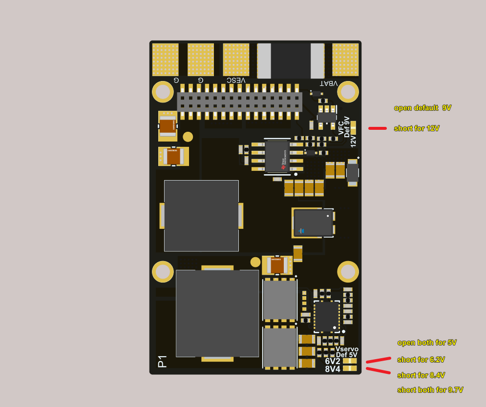
Output power: 8A cont./10A peak BEC. 5V, 6V, 8.4V (selectable)
Channels: 13x PWM (including LED)
Gyro: ICM42688 x 2 (SPI1 & SPI4)
Baro: DPS310 (I2C2)
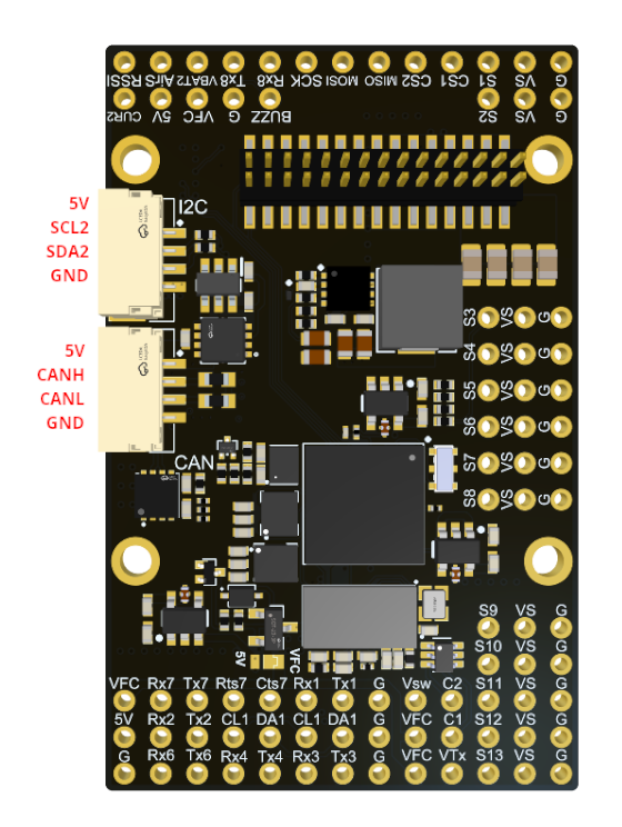
Peripherals: 7x UART, 2x I2C, 1x CAN
Measurements: 6x ADC (Vbat, Current, CB2, CU2, RSSI, AirSpeed)
High speed ports: MicroSD BlackBox, SPI3 on pin headers
Analog FPV: Switchable dual camera inputs, AT7456E OSD, 5V/9V/12V support at 5A (selectable)
Digital FPV: “DJI”-connector with SBUS and OSD communication
Current sensor: 165A cont. / 240A peak
FC BEC: 5V 3A cont. (for FC & peripherals)
FPV VTX BEC: 9V/12V 5A (selectable) and controlled by GPIO
Dual Camera inputs, GPIO selectable
Camera supply selectable between 5V and VTX supply
Dimensions: 54 x 36 x 13 mm
Pinout
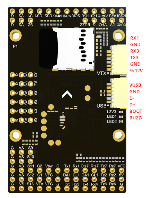
UART Mapping
The UARTs are marked Rn and Tn in the above pinouts. The Rn pin is the receive pin for UARTn. The Tn pin is the transmit pin for UARTn.
SERIAL0 -> USB (MAVLink2)
SERIAL1 -> UART1 (RX1 is SBUS in HD VTX connector)
SERIAL2 -> UART2 (GPS, DMA-enabled)
SERIAL3 -> UART3 (DisplayPort, DMA-enabled)
SERIAL4 -> UART4 (MAVLink2, Telem1)
SERIAL6 -> UART6 (RC Input, DMA-enabled)
SERIAL7 -> UART7 (MAVLink2, Telem2, DMA and flow-control enabled)
SERIAL8 -> UART8 (ESC Telemetry, RX8 on ESC connector for telem)
RC Input
RC input is configured by default via the USART6 RX input. It supports all unidirectional serial RC protocols except PPM.
For FPort the receiver must be tied to the USART6 TX6 pin , RSSI_TYPE set to 3, SERIAL6_OPTIONS = “7” (invert TX/RX, half duplex).
For full duplex CRSF/ELRS use both TX6 and RX6, and RSSI_TYPE set to 3 and provides telemetry.
If SBUS is used on HD VTX connector (DJI TX), then SERIAL1_PROTOCOl should be set to “23” and SERIAL6_PROTOCOL changed to something else. If UART1 is used for something else, be sure the RX2 pin on the HD VTX connector is left open.
FrSky Telemetry
FrSky Telemetry is supported using an unused UART, such as the T1 pin (UART1 transmit). You need to set the following parameters to enable support for FrSky S.PORT:
OSD Support
The TBS Lucid H7 Wing supports analog OSD using its onboard MAX7456 and simultaneously DisplayPort using TX3/RX3 on the HD VTX connector.
PWM Output
The TBS Lucid H7 Wing supports up to 13 PWM or DShot outputs. The pads for motor output M1 to M4 are provided on both the motor connectors and on separate pads, plus M9-13 on a separate pads for LED strip and other PWM outputs.
The PWM is in 4 groups:
PWM 1-2 in group1
PWM 3-4 in group2
PWM 5-6 in group3
PWM 7-10 in group4
PWM 11-12 in group5
PWM 13 in group6
Channels within the same group need to use the same output rate. If any channel in a group uses DShot then all channels in the group need to use DShot. Channels 1-10 support bi-directional Dshot.
Battery Monitoring
The board has a built-in voltage sensor and external current sensor input. The current sensor can read up to 130 Amps. The voltage sensor can handle up to 6S LiPo batteries.
The correct battery setting parameters are:
BATT_VOLT_MULT 11.0
BATT_AMP_PERVLT 40.0
Pads for a second analog battery monitor are provided. To use it:
BATT2_VOLT_MULT 11.0
BATT2_AMP_PERVLT as required
Analog RSSI and AIRSPEED inputs
Analog RSSI uses RSSI_ANA_PIN 8 Analog Airspeed sensor would use ARSPD_PIN 4
Compass
The TBS Lucid H7 Wing does not have a built-in compass, but you can attach an external compass using I2C on the SDA and SCL pads.
VTX power control
GPIO 81 controls the Vsw pins which can be set to output either VFC (9/12V) or 5V via a board jumper. Setting this GPIO high removes voltage supply to pins. RELAY2 is configured by default to control this GPIO and is low by default.
GPIO 83 controls the VTX BEC output to pins marked “9V/12V” included on the HD VTX connector and VFC pads and is included on the HD VTX connector. Setting this GPIO low removes voltage supply to this pin/pad. By default RELAY4 is configured to control this pin and sets the GPIO high.
Camera control
GPIO 82 controls the camera output to the connectors marked “C1” and “C2”. Setting this GPIO low switches the video input from C1 to C2. By default RELAY3 is configured to control this pin.
Loading Firmware
The TBS Lucid H7 Wing does not come with ArduPilot firmware pre-installed. Use the instructions here to load ArduPilot the first time Loading Firmware onto boards without existing ArduPilot firmware. Firmware for the TBS Lucid H7 Wing can be found here in sub-folders labeled “TBS_LUCID_H7_WING”.
Initial firmware load can be done with DFU by plugging in USB with the bootloader button pressed. Then you should load the “with_bl.hex” firmware, using your favourite DFU loading tool.
Once the initial firmware is loaded you can update the firmware using any ArduPilot ground station software. Updates should be done with the *.apj firmware files.