ARK FPV Flight Controller
Where to Buy
Features
STM32H743 32-bit processor
480MHz
2MB Flash
1MB RAM
Invensense IIM-42653 Industrial IMU with heater resistor
Bosch BMP390 Barometer
ST IIS2MDC Magnetometer
9x PWM Bidirectional-DSHOT capable
5x UARTS, one with hardware flow control
1x CAN
1x SPI, 1x I2C
5.5V - 54V (2S - 12S) input
12V, 2A output for video systems
5V, 2A output. 300ma for main system, 200ma for heater, 1.5A peripherals
Micro SD
USB-C
Dimensions
Size: 3.6 × 3.6 × 0.8 cm
Weight: 7.5g with MicroSD card
Pinout
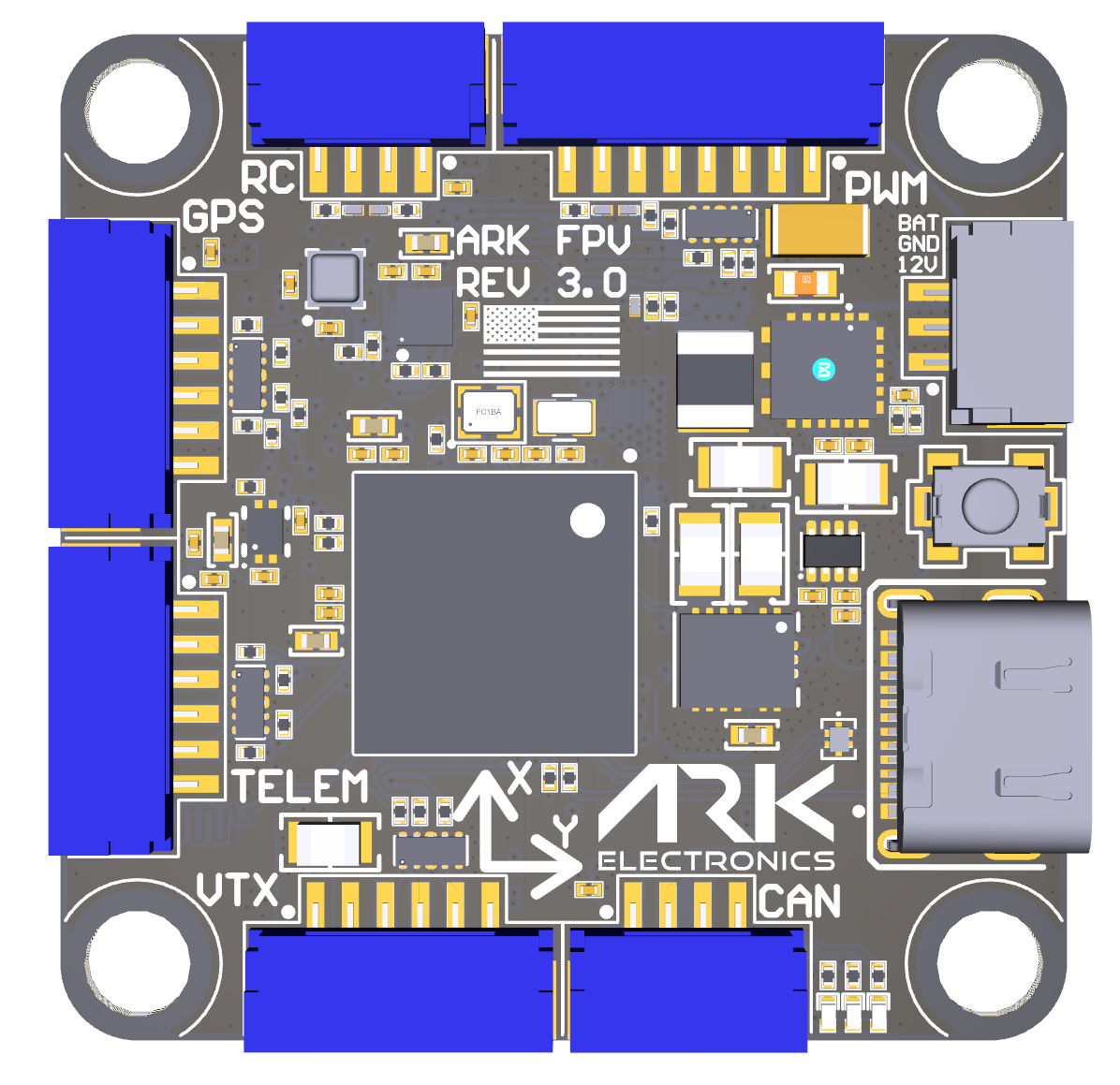
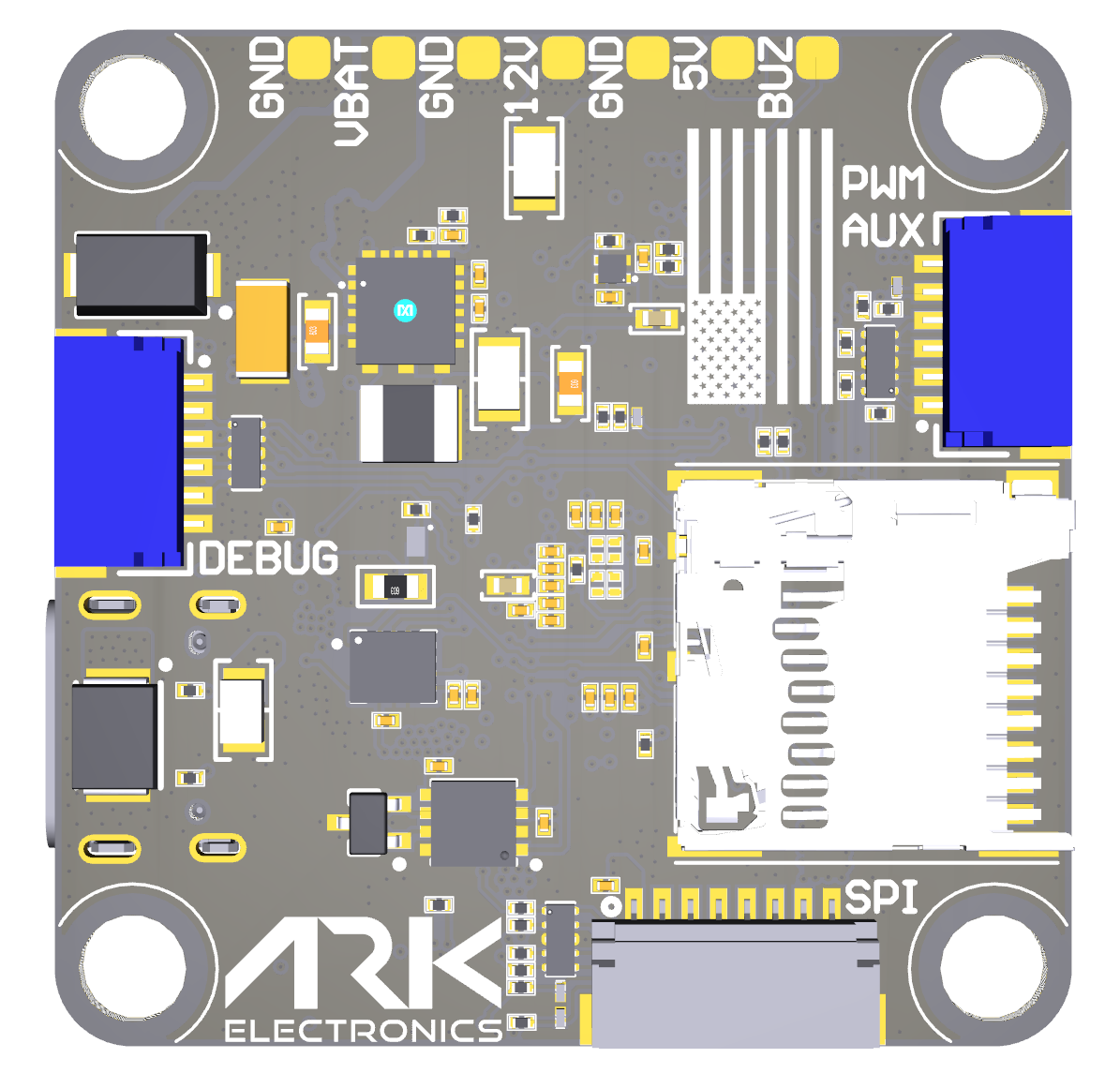
Connectors
PWM UART4 - 8 Pin JST-GH
Pin |
Signal Name |
Voltage |
|---|---|---|
1 |
VBAT IN |
5.5V-54V |
2 |
CURR_IN |
3.3V |
3 |
UART4_RX |
3.3V |
4 |
FMU_CH1 |
3.3V |
5 |
FMU_CH2 |
3.3V |
6 |
FMU_CH3 |
3.3V |
7 |
FMU_CH4 |
3.3V |
8 |
GND |
GND |
RC - 4 Pin JST-GH
Pin |
Signal Name |
Voltage |
|---|---|---|
1 |
5.0V |
5.0V |
2 |
USART6_RX_IN |
3.3V |
3 |
USART6_TX_OUTPUT |
3.3V |
4 |
GND |
GND |
PWM AUX - 6 Pin JST-SH
Pin |
Signal Name |
Voltage |
|---|---|---|
1 |
FMU_CH5 |
3.3V |
2 |
FMU_CH6 |
3.3V |
3 |
FMU_CH7 |
3.3V |
4 |
FMU_CH8 |
3.3V |
5 |
FMU_CH9 |
3.3V |
6 |
GND |
GND |
POWER AUX - 3 Pin JST-GH
Pin |
Signal Name |
Voltage |
|---|---|---|
1 |
12.0V |
12.0V |
2 |
GND |
GND |
3 |
VBAT IN/OUT |
5.5V-54V |
CAN - 4 Pin JST-GH
Pin |
Signal Name |
Voltage |
|---|---|---|
1 |
5.0V |
5.0V |
2 |
CAN1_P |
5.0V |
3 |
CAN1_N |
5.0V |
4 |
GND |
GND |
GPS - 6 Pin JST-GH
Pin |
Signal Name |
Voltage |
|---|---|---|
1 |
5.0V |
5.0V |
2 |
USART1_TX_GPS1 |
3.3V |
3 |
USART1_RX_GPS1 |
3.3V |
4 |
I2C1_SCL_GPS1 |
3.3V |
5 |
I2C1_SDA_GPS1 |
3.3V |
6 |
GND |
GND |
TELEM - 6 Pin JST-GH
Pin |
Signal Name |
Voltage |
|---|---|---|
1 |
5.0V |
5.0V |
2 |
UART7_TX_TELEM1 |
3.3V |
3 |
UART7_RX_TELEM1 |
3.3V |
4 |
UART7_CTS_TELEM1 |
3.3V |
5 |
UART7_RTS_TELEM1 |
3.3V |
6 |
GND |
GND |
VTX - 6 Pin JST-GH
Note
connector pinout not in same order as standard HD VTX cabling
Pin |
Signal Name |
Voltage |
|---|---|---|
1 |
12.0V |
12.0V |
2 |
GND |
GND |
3 |
UART5_TX_DisplayPort |
3.3V |
4 |
UART5_RX_DisplayPort |
3.3V |
5 |
USART2_RX_(SBUS) |
3.3V |
6 |
GND |
GND |
SPI (OSD or IMU) - 8 Pin JST-SH
Pin |
Signal Name |
Voltage |
|---|---|---|
1 |
5.0V |
5.0V |
2 |
SPI6_SCK |
3.3V |
3 |
SPI6_MISO |
3.3V |
4 |
SPI6_MOSI |
3.3V |
5 |
SPI6_nCS1 |
3.3V |
6 |
SPI6_DRDY1 |
3.3V |
7 |
SPI6_nRESET |
3.3V |
8 |
GND |
GND |
Flight Controller Debug - 6 Pin JST-SH
Pin |
Signal Name |
Voltage |
|---|---|---|
1 |
3V3_FMU |
3.3V |
2 |
USART3_TX_DEBUG |
3.3V |
3 |
USART3_RX_DEBUG |
3.3V |
4 |
FMU_SWDIO |
3.3V |
5 |
FMU_SWCLK |
3.3V |
6 |
GND |
GND |
UART Mapping
Name |
Function |
|---|---|
SERIAL0 |
USB |
SERIAL1 |
UART7 (Telem) |
SERIAL2 |
UART5 (DisplayPort HD VTX) |
SERIAL3 |
USART1 (GPS1) |
SERIAL4 |
USART2 (User, SBUS pin on HD VTX, RX only) |
SERIAL5 |
UART4 (ESC Telem, RX only) |
SERIAL6 |
USART6 (RC Input) |
SERIAL7 |
OTG2 (SLCAN) |
All UARTS support DMA. Any UART may be re-tasked by changing its protocol parameter.
RC Input
RC input is configured on the RX6 (UART6_RX) pin. It supports all RC protocols except PPM. See Radio Control Systems for details for a specific RC system. SERIAL6_PROTOCOL is set to “23”, by default, to enable this.
SBUS/DSM/SRXL connects to the RX6 pin.
FPort requires connection to TX6 and SERIAL6_OPTIONS be set to “7”.
CRSF also requires a TX6 connection, in addition to RX6, and automatically provides telemetry. Set SERIAL6_OPTIONS
SRXL2 requires a connection to TX6 and automatically provides telemetry. Set SERIAL6_OPTIONS to “4”.
Battery Monitoring
The board has a internal voltage sensor and connections on the ESC connector for an external current sensor input. The board supports up to 12S LiPo batteries.
The default battery parameters are:
BATT_MONITOR = 4
BATT_VOLT_PIN = 9
BATT_CURR_PIN = 12
BATT_VOLT_MULT = 21
BATT_AMP_PERVLT = 120
Compass
This autopilot has a built-in IIS2MDC compass.Due to potential interference, the autopilot is usually used with an external I2C compass as part of a GPS/Compass combination.
OSD Support
This flight controller has an MSP-DisplayPort output on a 6-pin DJI-compatible JST SH.
Note
connector pinout not in same order as standard HD VTX cabling
Motor Output
All outputs are capable of PWM and DShot. Motors 1-4 are capable of Bidirectional-DSHOT. All outputs in the motor groups below must be either PWM or DShot:
Motors 1-4 Group1 (TIM5)
Motors 5-8 Group2 (TIM8)
Motor 9 Group3 (TIM4)
Firmware
Firmware for this board can be found here in sub-folders labeled “ARK_FPV”
Loading Firmware
Initial firmware load can be done with DFU by plugging in USB with the BOOT button pressed. You can then load the bootloader using your favorite DFU tool. The bootloader can be found at https://firmware.ardupilot.org/Tools/Bootloaders/
Once the initial firmware is loaded you can update the firmware using any ArduPilot ground station software. Updates should be done with the *.apj firmware files.
Using the Debug Port as a Serial Port
The debug connector includes USART3, which is configured as a debug console by default. To use it as a regular serial port (SERIAL8), modify hwdef.dat to add USART3 to the end of the SERIAL_ORDER list:
SERIAL_ORDER OTG1 UART7 UART5 USART1 USART2 UART4 USART6 OTG2 USART3
And remove the debug console lines:
STDOUT_SERIAL SD3
STDOUT_BAUDRATE 57600
This requires building the firmware locally. See the Building the code Wiki section for build instructions.