YJUAV A6Ultra
The A6Ultra flight controller is manufactured and sold by YJUAV.
Features:
- MCU
STM32H743 32-bit processor running at 480MH
2MB Flash
1MB RAM
- Sensors
- IMUs:
2x ICM42688, ICM42652
- Baros:
Two barometers:2 x DPS310
Magnetometer: Built-in ITS8310 magnetometer
- Interfaces
Ethernet
Micro-C USB
MicroSD card slot
5 UARTs, 2 with hardware flow control
Safety Switch
2 Analog Power Monitor inputs
2 CAN ports
2 I2C ports
SPI port
Buzzer
RCin port
13 motor/servo outputs, 8 supporting BiDirDShot, 11 supporting DShot
Pinout
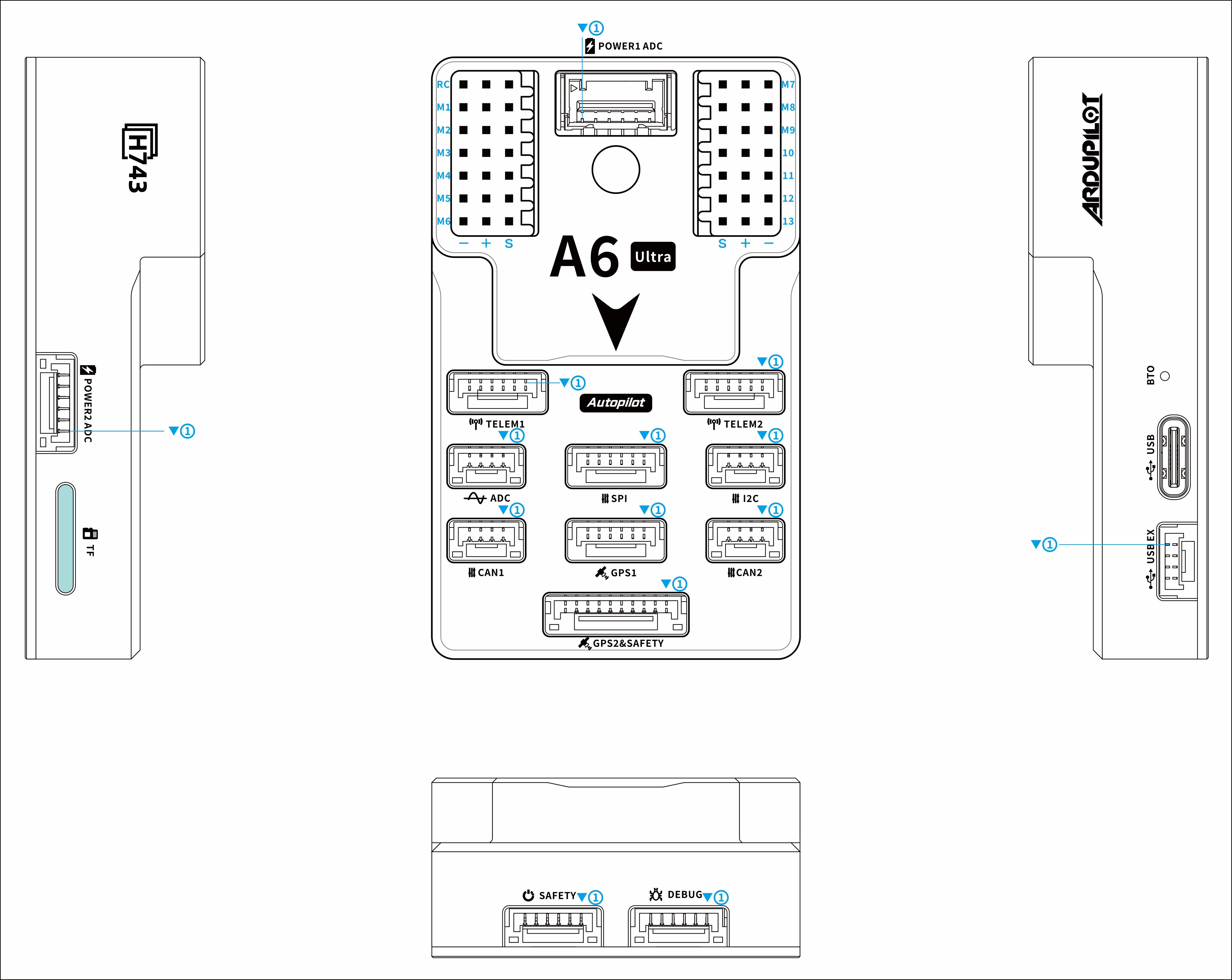
Connectors
POWER1 ADC
Pin |
Signal |
Volt |
|---|---|---|
1 |
VCC_IN |
+5V |
2 |
VCC_IN |
+5V |
3 |
BAT_CURRENT_ADC |
+3.3V |
4 |
BAT_VOLTAGE_ADC |
+3.3V |
5 |
GND |
GND |
6 |
GND |
GND |
POWER2 ADC
Pin |
Signal |
Volt |
|---|---|---|
1 |
VCC_IN |
+5V |
2 |
VCC_IN |
+5V |
3 |
BAT2_CURRENT_ADC |
+3.3V |
4 |
BAT2_VOLTAGE_ADC |
+3.3V |
5 |
GND |
GND |
6 |
GND |
GND |
TELEM1
Pin |
Signal |
Volt |
|---|---|---|
1 |
VCC |
+5V |
2 |
USART2_TX |
+3.3V |
3 |
USART2_RX |
+3.3V |
4 |
CTS |
+3.3V |
5 |
RTS |
+3.3V |
6 |
GND |
GND |
TELEM2
Pin |
Signal |
Volt |
|---|---|---|
1 |
VCC |
+5V |
2 |
USART6_TX |
+3.3V |
3 |
USART6_RX |
+3.3V |
4 |
CTS |
+3.3V |
5 |
RTS |
+3.3V |
6 |
GND |
GND |
ADC
Pin |
Signal |
Volt |
|---|---|---|
1 |
VCC |
+5V |
2 |
ADC_3V3 |
+3.3V |
3 |
ADC_6V6 |
+6.6V |
4 |
GND |
GND |
SPI
Pin |
Signal |
Volt |
|---|---|---|
1 |
VCC |
+5V |
2 |
SPI_SCK |
+3.3V |
3 |
SPI_MISO |
+3.3V |
4 |
SPI_MOSI |
+3.3V |
5 |
SPI_CS |
+3.3V |
6 |
GND |
GND |
I2C
Pin |
Signal |
Volt |
|---|---|---|
1 |
VCC |
+5V |
2 |
I2C4_SCL |
+3.3V |
3 |
I2C4_SDA |
+3.3V |
4 |
GND |
GND |
CAN1
Pin |
Signal |
Volt |
|---|---|---|
1 |
VCC |
+5V |
2 |
CAN1_P |
+3.3V |
3 |
CAN1_N |
+3.3V |
4 |
GND |
GND |
CAN2
Pin |
Signal |
Volt |
|---|---|---|
1 |
VCC |
+5V |
2 |
CAN2_P |
+3.3V |
3 |
CAN2_N |
+3.3V |
4 |
GND |
GND |
GPS1
Pin |
Signal |
Volt |
|---|---|---|
1 |
VCC |
+5V |
2 |
USART3_TX |
+3.3V |
3 |
USART3_RX |
+3.3V |
4 |
I2C2_SCL |
+3.3V |
5 |
I2C2_SDA |
+3.3V |
6 |
GND |
GND |
GPS2&SAFETY
Pin |
Signal |
Volt |
|---|---|---|
1 |
VCC |
+5V |
2 |
USART1_TX |
+3.3V |
3 |
USART1_RX |
+3.3V |
4 |
I2C3_SCL |
+3.3V |
5 |
I2C3_SDA |
+3.3V |
6 |
SAFETY_SW |
+3.3V |
7 |
SAFETY_SW_LED |
+3.3V |
8 |
3V3_OUT |
+3.3V |
9 |
BUZZER |
+3.3V |
10 |
GND |
GND |
DEBUG
Pin |
Signal |
Volt |
|---|---|---|
1 |
VCC |
+5V |
2 |
UART7_TX |
+3.3V |
3 |
UART7_RX |
+3.3V |
4 |
SWDIO |
+3.3V |
5 |
SWCLK |
+3.3V |
6 |
GND |
GND |
SAFETY
Pin |
Signal |
Volt |
|---|---|---|
1 |
3V3_OUT |
+3.3V |
2 |
SAFETY_SW |
+3.3V |
3 |
SAFETY_SW_LED |
+3.3V |
4 |
UART8_TX(SBUS_OUT) |
+3.3V |
5 |
RSSI |
+3.3V |
6 |
GND |
GND |
USB EX
Pin |
Signal |
Volt |
|---|---|---|
1 |
VCC_IN |
+5V |
2 |
DM |
+3.3V |
3 |
DP |
+3.3V |
4 |
GND |
GND |
UART Mapping
SERIAL0 -> USB (OTG1)
SERIAL1 -> USART2 (Telem1)
SERIAL2 -> USART6 (Telem2)
SERIAL3 -> USART3 (GPS1)
SERIAL4 -> USART1 (GPS2)
SERIAL5 -> UART8 (USER) TX only, normally used for SBUS_OUT with protocol change
SERIAL6 -> UART7 (USER/Debug), NODMA
SERIAL7 -> USB2 (OTG2)
RC Input
The RCIN pin is mapped to a timer input instead of the UART, and can be used for all ArduPilot supported receiver protocols, except CRSF/ELRS and SRXL2 which require a true UART connection. However, FPort, when connected in this manner, can provide RC without telemetry.
To allow CRSF and embedded telemetry available in Fport, CRSF, and SRXL2 receivers, a full UART must be used. For example, UART1 can have its protocol changed from the default GPS protocol for GPS2 to RX input protocol:
With this option, SERIAL4_PROTOCOL must be set to “23”, and:
PPM is not supported.
SBUS/DSM/SRXL connects to the RX1 pin.
FPort requires connection to TX1 and RX1. See FPort Receivers.
CRSF also requires a TX1 connection, in addition to RX1, and automatically provides telemetry.
SRXL2 requires a connection to TX1 and automatically provides telemetry. Set SERIAL4_OPTIONS to “4”.
Any UART can be used for RC system connections in ArduPilot also, and is compatible with all protocols except PPM. See Radio Control Systems for details.
PWM Output
The A6Ultra supports up to 13 PWM outputs,support all PWM protocols. All 13 PWM outputs have GND on the bottom row, 5V on the middle row and Signal on the top row.
The 13 PWM outputs are in 4 groups:
PWM 1, 2, 3 and 4 in group1
PWM 5, 6, 7 and 8 in group2
PWM 9, 10, 11 in group3
PWM 12, 13 in group4 (PWM only)
Channels 1-8 support bi-directional Dshot. Channels 1-11 support DShot. Channels within the same group need to use the same output rate. If any channel in a group uses DShot, then all channels in that group need to use DShot.
GPIOs =====BATT2_MONITOR 4
BATT2_VOLT_PIN 12
BATT2_CURR_PIN 16
BATT2_VOLT_MULT 21.0 (may need adjustment if supplied monitor is not used)
BATT2_AMP_PERVLT 34.6 (may need adjustment if supplied monitor is not used)
All 13 PWM channels can be used for GPIO functions (relays, buttons, RPM etc).
The pin numbers for these PWM channels in ArduPilot are shown below:
PWM Channels |
Pin |
PWM Channels |
Pin |
|---|---|---|---|
PWM1 |
50 |
PWM8 |
57 |
PWM2 |
51 |
PWM9 |
58 |
PWM3 |
52 |
PWM10 |
59 |
PWM4 |
53 |
PWM11 |
60 |
PWM5 |
54 |
PWM12 |
61 |
PWM6 |
55 |
PWM13 |
62 |
PWM7 |
56 |
Analog inputs
The A6Ultra flight controller has 7 Analog inputs
ADC Pin4 -> Battery Current
ADC Pin2 -> Battery Voltage
ADC Pin16 -> Battery2 Current
ADC Pin12 -> Battery2 Voltage
ADC Pin8 -> ADC 3V3 Sense
ADC Pin10 -> ADC 6V6 Sense ADC Pin11 -> RSSI voltage monitoring
Battery Monitor
The board has voltage and current sensor inputs on the POWER1_ADC and POWER2_ADC connector.
The correct battery setting parameters are:
Battery1 monitor:
BATT_MONITOR = 4
BATT_VOLT_PIN = 2
BATT_CURR_PIN = 4
BATT_VOLT_MULT = 21.0 (may need adjustment if supplied monitor is not used)
BATT_AMP_PERVLT = 34.6 (may need adjustment if supplied monitor is not used)
Battery2 monitor:
BATT2_MONITOR = 4
BATT2_VOLT_PIN = 12
BATT2_CURR_PIN = 16
BATT2_VOLT_MULT = 21.0 (may need adjustment if supplied monitor is not used)
BATT2_AMP_PERVLT = 34.6 (may need adjustment if supplied monitor is not used)
Loading Firmware
The A6Ultra flight controller comes pre-installed with an ArduPilot compatible bootloader, allowing the loading of *.apj firmware files with any ArduPilot compatible ground station.