mRo Nexus
The mRo Nexus is new member of mRo’s Pixracer autopilot family.
Overview
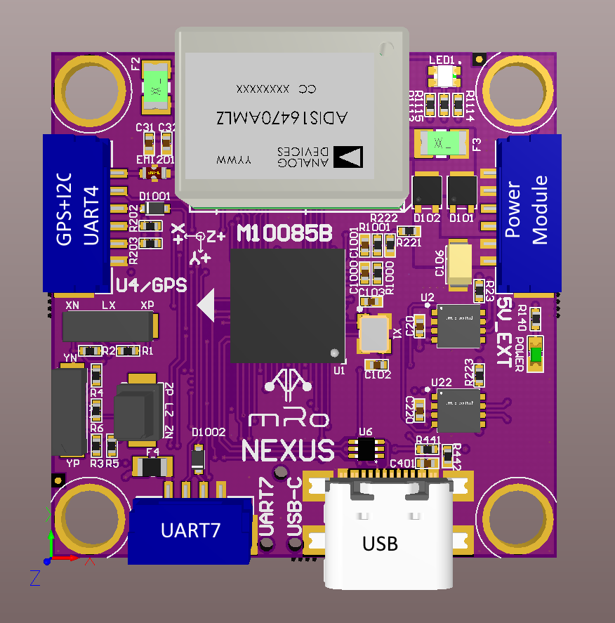
The mRo Nexus is a member of the next generation of mRobotics’ family of Pixracer autopilots. It has been designed for ultra compact applications which primarily use CAN peripherals, as well as standard GPS/Compass or Airspeed sensors. It includes an integrated ADS-B receiver for avoidance.
Tip
At time of writing the autopilot is still being evolved/improved. The final version may very slightly from the information provided here.
Specifications
Processor:
MCU - STM32H743VIH6
2MB flash allows full features of ArduPilot to be flashed
Sensors
Gyro/Accelerometer: Invensense ICM-40609D / Gyro (? KHz)
Barometer: DSP310
RM3100 Precision Compass
Power
5-5.5VDC from USB or PowerBrick connector. Optional/recommended ACSP4 +5V/+12V Power Supply.
Ultra low noise LDOs for sensors and FMU
Interfaces/Connectivity
Dual CAN/DroneCAN ports
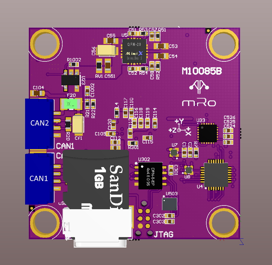
MicroSD card reader
Micro-C USB
RGB LED
GPS (serial + I2C)
UART for serial RC input
Connectors: GPS+I2C (USART4),CAN1, CAN2, USART7 (TxD, RxD), POWER-BRICK(VDD, Voltage, Current, GND).
Dimensions
Weight ?
Size
Connector pin assignments
Unless noted otherwise all connectors are JST GH
UART7 connector
PIN |
SIGNAL |
VOLTAGE/TOLERANCE |
|---|---|---|
1 |
+5V |
+5V |
2 |
TX1 |
+3.3V/5V |
3 |
RX1 |
+3.3V/5V |
4 |
GND |
GND |
USART4 (GPS+I2C) connector
PIN |
SIGNAL |
VOLTAGE/TOLERANCE |
|---|---|---|
1 |
+5V |
+5V |
2 |
TX |
+3.3V/5V |
3 |
RX |
+3.3V/5V |
4 |
SCL |
+3.3V/5V |
5 |
SDA |
+3.3V/5V |
6 |
GND |
GND |
CAN1 and CAN2 connectors
PIN |
SIGNAL |
VOLTAGE/TOLERANCE |
|---|---|---|
1 |
+5V |
+5V |
2 |
CH |
+3.3V/5V |
3 |
CL |
+3.3V/5V |
4 |
GND |
GND |
Power connector
PIN |
SIGNAL |
VOLTAGE/TOLERANCE |
|---|---|---|
1 |
+5V in |
+5V |
2 |
+5V in |
+5V |
3 |
CURR sense in |
+3.3V/5V |
4 |
VOLT sense in |
+3.3V/5V |
5 |
GND |
GND |
6 |
GND |
GND |
Default UART order
Parameter |
Default Protocol** |
Connector/Suggested Use |
|---|---|---|
SERIAL0 |
console |
USB |
SERIAL1 |
Telemetry1 |
UART7/Serial RC input |
SERIAL2 |
Telemetry2 |
USB (second composite USB interface)/SLCAN |
SERIAL3 |
GPS1 |
UART4/GPS |
** User may change SERIALx_PROTOCOL as required for application