MicoAir405v2/ Mini
The MicoAir405v2 is a autopilot produced by MicoAir.
MINI
Where to Buy
Mini
Specifications
Processor
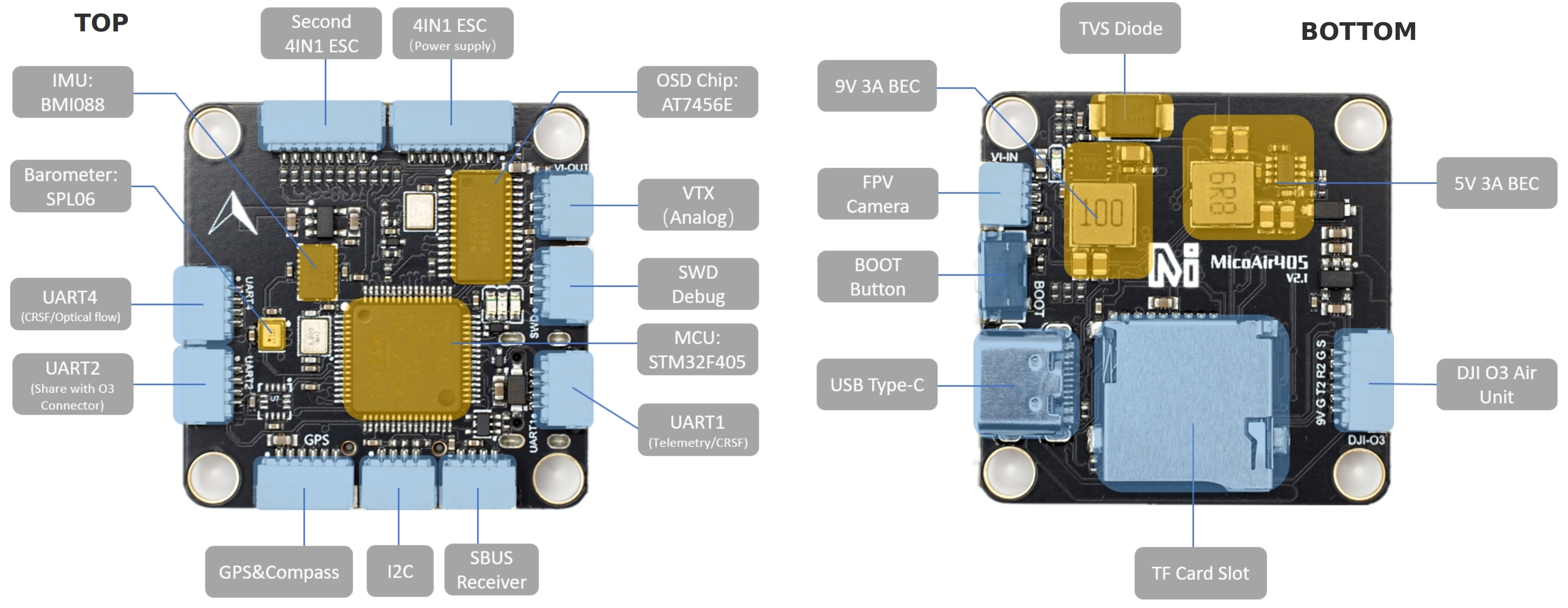
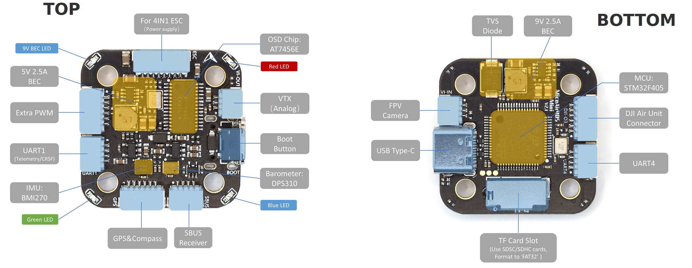
STM32F405 microcontroller
AT7456E OSD
Sensors
BMI088 IMU (accel and gyro)/ Mini: BMI270 IMU
SPL06 barometer / Mini: DPS310
Power
2S - 6S Lipo input voltage with voltage monitoring
9V 3A (Mini: 2.5A) BEC for powering Video Transmitter
5V 3A (Mini:2.5A) BEC for peripherals
Interfaces
10x PWM outputs/ Mini: 9 PWM outputs
1x SBUS RC input
6x UARTs/serial for GPS and other peripherals
1x I2C port for external compass
Camera/VTX/HD(DJI) VTX connectors
Micro-C USB port
MicroSD Card Slot for logging
External current monitor input
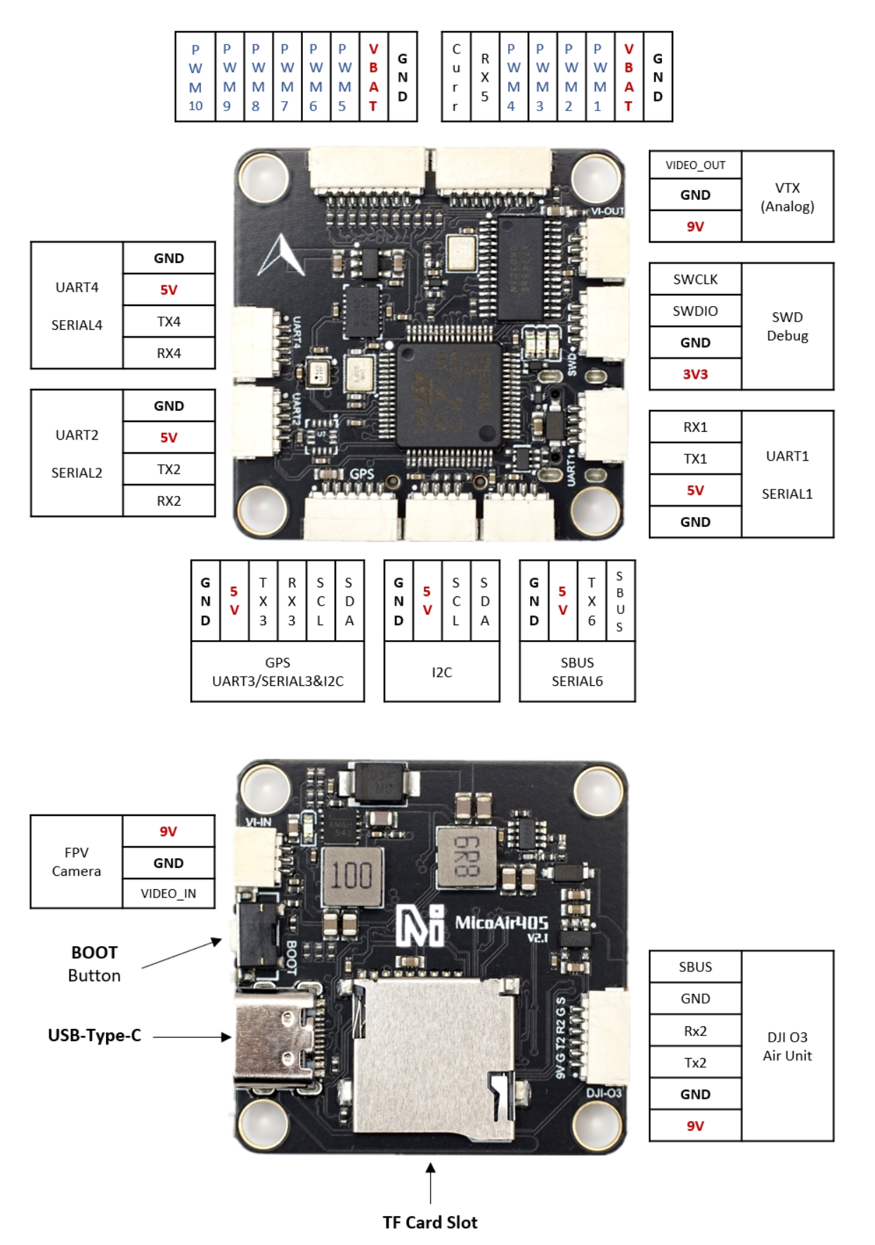
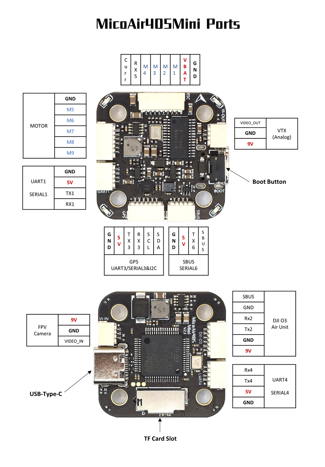
Pinout
Mini
UART Mapping
The UARTs are marked Rxn and Tn in the above pinouts. The Rxn pin is the receive pin for UARTn. The Txn pin is the transmit pin for UARTn.
SERIAL0 -> USB
SERIAL1 -> UART1 (MAVLink2, DMA-enabled)
SERIAL2 -> UART2 (DisplayPort, TX2 only DMA-enabled)
SERIAL3 -> UART3 (GPS)
SERIAL4 -> UART4 (MAVLink2, TX only DMA-enabled)
SERIAL5 -> UART5 (RX pin only,ESC Telemetry)
SERIAL6 -> UART6 (RX6 is inverted from SBUS pin, no DMA on TX6)
RC Input
The default RC input is SBUS only on SBUS pin. PPM is not supported. Other RC protocols must use another UART port such as UART1 or UART4, and set its protocol to receive RC data: SERIALx_PROTOCOL=23 and change SERIAL6_PROTOCOL to something other than its default protocol of ‘23’. If using CRSF/ELRS, UART1 should be used since it has full DMA. If using another UART for RC input:
FPort requires connection to the TX of the UART and
SERIALx_OPTIONSbe set to “7”.CRSF also requires a TX connection, and automatically provides telemetry. Set
SERIALx_OPTIONSto “0”.SRXL2 requires a connection to TX and automatically provides telemetry. Set
SERIALx_OPTIONS>to “4”.
OSD Support
The MicoAir405v2 supports analog OSD using OSD_TYPE 1 (MAX7456 driver) using the CAM and VTX connectors. DisplayPort HD OSD via the DJI connector is enabled simultaneously by OSD_TYPE2 = 5.
HD VTX Support
The SH1.0-6P connector supports a standard DJI HD VTX connection. Pin 1 of the connector is 9v so be careful not to connect this to a peripheral requiring 5v.
PWM Output
The MicoAir405v2 supports up to 10 PWM outputs(Mini supports 9). Outputs 1-8 also support DShot. Outputs 1-4 support bi-directional DShot. Outputs are grouped and each group must use the same output protocol:
1,2,5,6 are group1
3, 4 are group 2
7,8 are group 3
9,10 are in group 4
Note
for users migrating from BetaflightX quads, the first four outputs M1-M4 have been configured for use with existing motor wiring using these default parameters:
FRAME_CLASS = 1 (Quad)
FRAME_TYPE = 12 (BetaFlightX)
Battery Monitoring
The board has a built-in voltage sensor via the VBAT pin, but no internal current sensor. An external current sensor can be connected to the Curr pin. Default parameters for both internal voltage and external current monitoring are set by default to :
BATT_VOLT_MULT 21.2
BATT_AMP_PERVLT 40.2
Compass
The MicoAir405v2/Mini do not have a built-in compass, but you can attach an external compass using I2C on the SDA and SCL connector.
Firmware
Firmware for this board can be found here in sub-folders labeled “MicoAir405v2” or MicoAir405Mini”.
Loading Firmware
Initial firmware load can be done with DFU by plugging in USB with the bootloader button pressed. Then you should load the “with_bl.hex” firmware, using your favorite DFU loading tool.
Once the initial firmware is loaded you can update the firmware using any ArduPilot ground station software. Updates should be done with the “*.apj” firmware files.