SpeedyBee F405 AIO 40A Bluejay
The SpeedyBee F405 AIO is a flight controller produced by SpeedyBee.
Where To Buy
Features
MCU: STM32F405 32-bit processor. 1024Kbytes Flash
IMU: ICM-42688P (SPI)
Barometer: SPA06-003
USB VCP Driver (all UARTs usable simultaneously; USB does not take up a UART)
6 UARTS (UART1 tied internally to BT module which is not currently supported by ArduPilot)
8MBytes for logging
5V Power Out: 2.0A max
Dimensions: 33x33mm
Mounting Holes: Standard 25.5/25.5mm square to center of holes
Weight: 13.6g
Built-in 40A BlueJay 4in1 ESC (Bluejay JH-40 48kHz)
Input Voltage: 3S-6S Lipo
Continuous Current: 40A
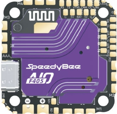
Pinout
Note
S pin for “Meteor LED” does not work with this firmware
UART Mapping
The UARTs are marked Rn and Tn in the above pinouts. The Rn pin is the receive pin for UARTn. The Tn pin is the transmit pin for UARTn.
Name |
UART |
Default Protocol |
|---|---|---|
SERIAL0 |
USB |
MAVLink2 |
SERIAL1 |
USART1 |
(WiFi module, not usable by ArduPilot) |
SERIAL2 |
USART2 |
(USER, RX pin only, tied to inverted SBUS pin |
SERIAL3 |
USART3 |
(DisplayPort) |
SERIAL4 |
UART4 |
(User) |
SERIAL5 |
UART5 |
(GPS) |
SERIAL6 |
UART6 |
(RCin, DMA-enabled) |
RC Input
RC input is configured on UART6. It supports all RC protocols except PPM, FPort, and SBUS. See Radio Control Systems for details for a specific RC system. SERIAL6_PROTOCOL is set to “23”, by default, to enable this.
FPort requires an external bi-directional inverter and connects to TX 6 with SERIAL6_OPTIONS set to “7”.
CRSF requires a TX6 connection, in addition to RX6, and automatically provides telemetry.
SRXL2 requires a connection to TX6 and automatically provides telemetry. Set SERIAL6_OPTIONS set to “4”.
SBUS can be directly connected to the SBUS pin which ties through an inverter to the RX2 pin. SERIAL2_PROTOCOL must be set to “23” and SERIAL6_PROTOCOL must be changed to something else than “23”
Any UART can be used for RC system connections in ArduPilot also, and is compatible with all protocols except PPM. See Radio Control Systems for details.
OSD Support
The SpeedyBee F405 AIO supports OSD using OSD_TYPE = 1 (MAX7456 driver). The defaults are also setup to allow DJI Goggle OSD support on UART3. Both the internal analog OSD and the DisplayPort OSD can be used simultaneously by setting OSD_TYPE2 = 5
PWM Output
The SpeedyBee F405 AIO supports up to 5 PWM outputs. The pads for motor output ESC1 to ESC4 on the above diagram are the first 4 outputs.All 5 outputs support DShot.
The PWM are in 3 groups:
PWM 1-2: Group 1
PWM 3-4: Group 2
LED: Group 3
Channels within the same group need to use the same output rate. If any channel in a group uses DShot then all channels in the group need to use DShot. PWM 1-4 support bidirectional dshot.
Battery Monitoring
The board has a builtin voltage sensor. The voltage sensor can handle 2S to 6S LiPo batteries. The integrated ESC also provides a current sensor.
The correct battery setting parameters are:
BATT_MONITOR = 4
BATT_VOLT_PIN = 10
BATT_CURR_PIN = 12
BATT_VOLT_MULT = 11
BATT_AMP_PERVLT = 39.4
These are set by default in the firmware and shouldn’t need to be adjusted
Compass
The SpeedyBee F405 AIO does not have a builtin compass but an external compass can be attached using the SDA/SCL pins.
Camera Control
The CC pin is a GPIO (pin 70) and is assigned by default to RELAY2 functionality. This pin can be controlled via GCS or by RC transmitter using the Auxiliary Function feature.
NeoPixel LED
The board includes a NeoPixel LED pad.
Firmware
Firmware for this board can be found: here in sub-folders labeled “SpeedyBeeF405AIO”.
Loading Firmware
Initial firmware load can be done with DFU by plugging in USB with the bootloader button pressed. Then you should load the “with_bl.hex” firmware, using your favorite DFU loading tool.
Once the initial firmware is loaded you can update the firmware using any ArduPilot ground station software. Updates should be done with the *.apj firmware files.