iFlight Thunder H7
The iFlight Thunder H7 is a flight controller produced by iFlight.
Specifications
Processor
MCU - STM32H743 32-bit processor running at 480 MHz
Onboard Flash: 1GBit (appears a non-removeable SD card for logging)
Sensors
IMU - ICM42688P
Barometer - SPL06-001
Power
Battery input voltage: 2S-6S
BEC 5V 1.5A
Switchable TX power BEC 10V 1.5A
Interfaces
9x PWM Outputs (8 Motor Output, 1 LED)
6x UARTs/serial for GPS and other peripherals. All UARTS support hardware inversion. SBUS, SmartPort, and other inverted protocols work on any UART without “uninvert hack”
2x I2C ports for external compass, airspeed, etc.
USB-C port and boot button on separate dongle for ease of access
Size and Dimensions
42mm x 42mm
30.5*30.5mm mount holes 4mm dia
14g
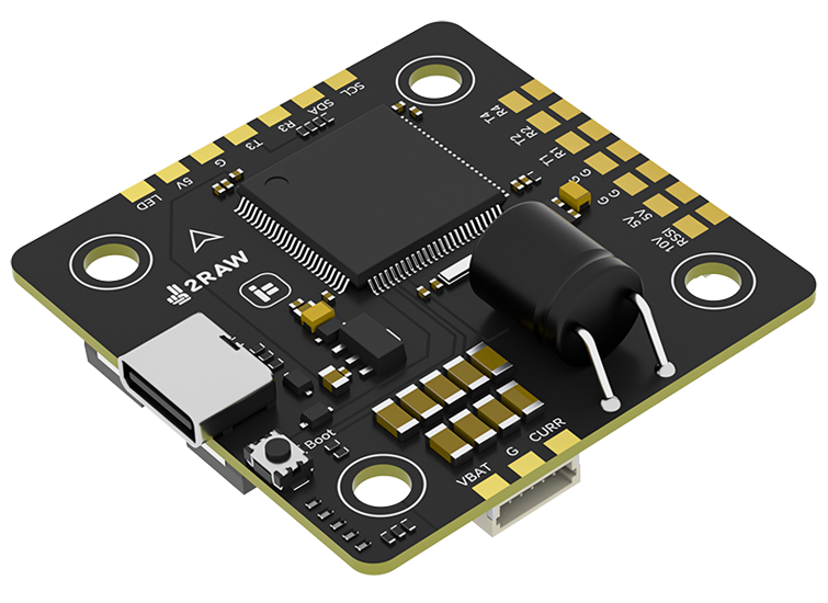
Pinout
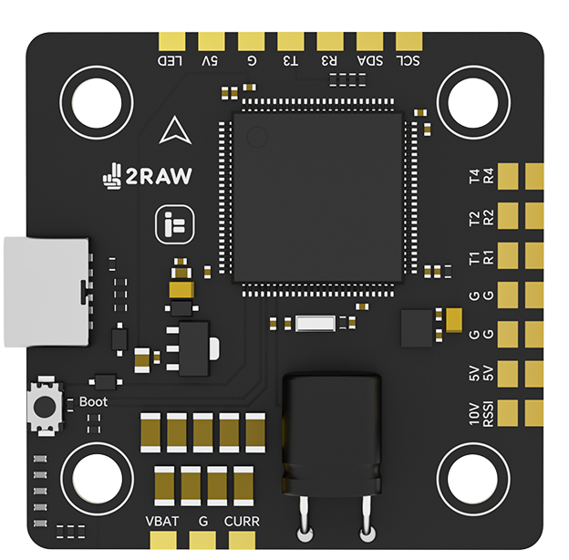
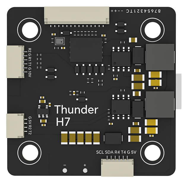
UART Mapping
The UARTs are marked Rn and Tn in the above pinouts. The Rn pin is the receive pin for UARTn. The Tn pin is the transmit pin for UARTn.
SERIAL0 -> USB
SERIAL1 -> UART1 (DisplayPort, DMA-enabled)
SERIAL2 -> UART2 (RC, DMA-enabled)
SERIAL3 -> UART3 (GPS, DMA-enabled)
SERIAL4 -> UART4 (GPS, DMA-enabled)
SERIAL6 -> UART6 (ESC Telemetry)
RC Input
RC input is configured on the R2 (UART2_RX) pin. It supports all serial RC protocols. Use T2 also for duplex protocols such as CRSF. For protocols requiring half-duplex serial to transmit telemetry (such as FPort) you should setup SERIAL2 with half-duplex and attach input to T2.
FrSky Telemetry
FrSky Telemetry could supported using the T3 pin (UART3 transmit) (or any other free UART). You need to set the following parameters to enable support for FrSky S.PORT
SERIAL3_PROTOCOL 10
SERIAL3_OPTIONS 7
OSD Support
The iFlight Thunder H7 supports MSP DisplayPort OSDs using OSD_TYPE 5 and SERIAL1 by default (on HD VTX connector)
PWM Output
The iFlight Thunder H7 supports up to 9 PWM outputs. The pads for motor output M1 to M8 are provided in the motor connector, plus M9 on a separate pad for LED strip or another PWM output.
The PWM is in 5 groups:
PWM 1-2 in group1
PWM 3-6 in group2
PWM 7-8 in group3
PWM 9 in group4
Channels within the same group need to use the same output rate. If any channel in a group uses DShot then all channels in the group need to use DShot. Channels 1-8 support bi-directional dshot.
Battery Monitoring
The board has a built-in voltage senso and a current sensor input. The voltage sensor can handle up to 6S LiPo batteries.
The correct battery setting parameters are:
BATT_MONITOR = 4
BATT_VOLT_PIN = 11
BATT_CURR_PIN = 13
BATT_VOLT_MULT = 11.1
BATT_AMP_PERVLT = 64 (needs to be adjusted for whatever current sensor is being used)
Compass
The iFlight Thunder H7 does not have a built-in compass, but you can attach an external compass using I2C on the SDA and SCL pads.
VTX power control
GPIO 81 controls the VTX BEC output to pins marked “10V”. Setting this GPIO low removes voltage supply to pins. By default RELAY2 is configured to control this pin and sets the GPIO high.
Firmware
Firmware for this board can be found here in sub-folders labeled “IFLIGHT_2RAW_H7”.
Loading Firmware
Initial firmware load can be done with DFU by plugging in USB with the bootloader button pressed. Then you should load the “with_bl.hex” firmware, using your favourite DFU loading tool.
Once the initial firmware is loaded you can update the firmware using any ArduPilot ground station software. Updates should be done with the *.apj firmware files.