Matek F405 TE Family
This family consists of:
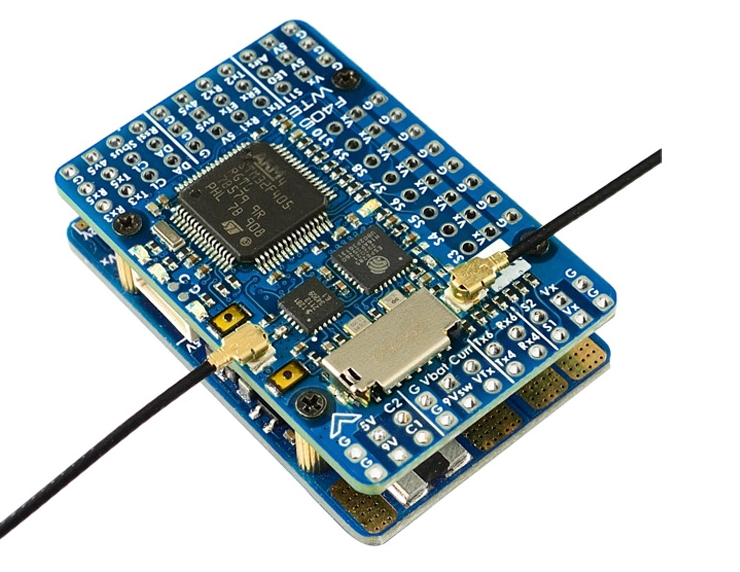
Matek F405-WTE
Matek F405-WMN
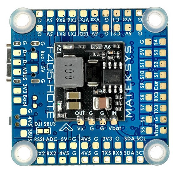
Matek F405-HDTE
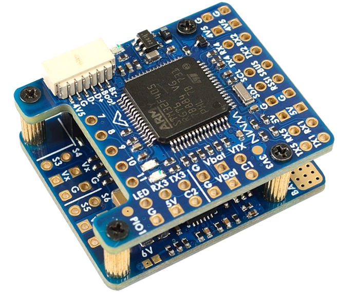
Matek F405-miniTE
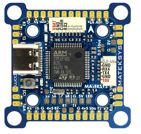
the above images and some content courtesy of mateksys.com
Specifications
Processor
STM32F405RGT6 ARM
OSD: AT7456E
16MB Flash for data logging, WTE has microSD card reader instead of flash chip
ESP8285 (WTE only) for ELRS or ESP WIFI Telemetry
Sensors
ICM42688-P
SPL06-001 barometer
Voltage sensor (30V max, 60V max for -HDTE)
Current Sensor (220A -WTE, 132A -WMN, input pin -miniTE/HDTE)
Power Input
6V ~ 30V DC input power (9v - 60V for -HDTE)
BECs
Board |
Typical Use |
Voltage |
Current(cont/peak) |
|---|---|---|---|
WTE |
Peripherals |
5V |
2A/3A |
Servos |
5V,6V, or 7.2V |
8A/10A |
|
VTX/CAM |
9V or 12V |
2A/3A |
|
WMN |
Peripherals |
5V |
1.5A/1.5A |
Servos |
5V or 6V |
5A/5A |
|
HDTE |
Peripherals |
5V |
1.5A/1.5A |
Servos/VTX |
9V, 12V, or 16V |
1-2A depending on input |
|
miniTE |
Peripherals |
5V |
1.7A/1.7A |
VTX |
10V |
1.4A/1.4A |
Interfaces
Board |
UARTS |
PWM |
I2C |
Buzzer |
ADC |
SD Card |
USB |
|---|---|---|---|---|---|---|---|
WTE |
6 |
12 |
1 |
Yes |
4 |
Yes |
Remote |
WMN |
5 |
12 |
1 |
Yes |
3 |
No |
Remote |
HDTE |
6 |
12 |
1 |
Yes |
4 |
Yes |
Yes |
miniTE |
6 |
12 |
1 |
Yes |
3 |
Yes |
Yes |
1x RC input PWM/PPM, SBUS
Dual Switchable Camera inputs on WTE and WMN, switched GPIO pin on HDTE and miniTE
Switchable VTX supply on WTE, miniTE, and HDTE; switched GPIO pin on WMN
ESP ELRS Receiver or ESP WIFI Telemetry
The Matek F405-WTE includes an ESP8285 processor that can be flashed to provide either ELRS RC/Telem Receiver onboard, or to provide ESP WIFI Telemetry. See the setup and flashing instructions provided on the Mateksys website.
Camera and Supply Switch
Switching between the two camera inputs, C1 (default on) or C2, and between on (default) and off of Vsw (jumper selectable supply) on some boards, can be implemented using the Relay function of ArduPilot and assigning the relays to an RCx_OPTION switch on the transmitter.
Note
some boards implement one or the other of the camera switch and video power supply switch,instead of both, but those boards bring the controlling GPIO pin out to a pad for use externally.
Set the RELAYx_PIN to “81” for on/off of Vsw, and to “82” to control the camera switching.
Then select an RC channel for control (Chx) and set its RCx_OPTION to the appropriate Relay (1-4) that you had set its pin parameter above.
For example, use Channel 10 to control the camera switch using Relay 2:
RELAY2_PIN = “82”
RC10_OPTION = “34” (Relay2 Control)
Note
setting Relay on/high assigned for Vsw will turn off that supply. Likewise, setting on/high for the Relay assigned for camera, will switch from Camera 1 to Camera 2.
Default UART order
SERIAL0 = console = USB
SERIAL1 = Telemetry1 = USART1 (has DMA)
SERIAL2 = Telemetry2 = USART3
SERIAL3 = GPS1 = UART5
SERIAL4 = GPS2 = UART4
SERIAL5 = USER = USART6 (has DMA on TX only)(not available on WMN)
SERIAL6 = USER = USART2 (TX only unless BRD_ALT_CONFIG = 1, then RX available also) and has DMA
Serial port protocols (Telem, GPS, etc.) can be adjusted to personal preferences.
RC Input
The RX2 pin, which by default is mapped to a timer input, can be used for all ArduPilot supported receiver protocols, except CRSF/ELRS and SRXL2 which require a true UART connection. However, FPort, when connected in this manner, will only provide RC without telemetry.
To allow CRSF and embedded telemetry available in Fport, CRSF, and SRXL2 receivers, the RX2 pin can also be configured to be used as true UART RX pin for use with bi-directional systems by setting the BRD_ALT_CONFIG to “1” so it becomes the SERIAL6 port’s RX input pin.
With this option, SERIAL6_PROTOCOL must be set to “23”, and:
PPM is not supported.
SBUS/DSM/SRXL connects to the RX2 pin, but SBUS requires that the SERIAL6_OPTIONS be set to “3”.
FPort requires connection to TX2 and SERIAL6_OPTIONS be set to “7”.
CRSF also requires a TX2 connection, in addition to Rx6, and automatically provides telemetry. Set SERIAL6_OPTIONS to “0”.
SRXL2 requires a connection to TX2 and automatically provides telemetry. Set SERIAL6_OPTIONS to “4”.
Any UART can be used for RC system connections in ArduPilot also, and is compatible with all protocols except PPM. See Radio Control Systems for details.
Dshot capability
All motor/servo outputs are Dshot(except outputs 9/10/11) and PWM capable. However, mixing Dshot and normal PWM operation for outputs is restricted into groups, ie. enabling Dshot for an output in a group requires that ALL outputs in that group be configured and used as Dshot, rather than PWM outputs. The output groups that must be the same (PWM rate or Dshot, when configured as a normal servo/motor output) are: 1/2, 3/4, 5/6/7/8, 9/10, 11, and 12 (LED).
Where to Buy
see this list of Mateksys Distributors
Battery Monitor Settings
These should already be set by default. However, if lost or changed:
Enable Battery monitor with these parameter settings :
Then reboot.
BATT_VOLT_MULT 21.0
BATT_AMP_PERVLT 66.7
Note
The -WMN uses a different current sensor and the default value for BATT_AMP_PERVLT should be changed to 40.
Note
this autopilot uses a high precision current sensor which is sensitive to ESC switching noise. Be sure to use the bypass capacitor provided. In some cases, the ESCs themselves will need additional 200-330uF low ESR capacitors on their power inputs, if they do not incorporate them already. See Matek FAQs for more information.
Firmware
Firmware for these boards can be found here in sub-folders labeled “MatekF405-TE”.