DAKEFPV F405
The DAKEFPV F405 is a flight controller produced by DAKEFPV.
Features
MCU - STM32F405 32-bit processor. 1024Kbytes Flash
IMU - Dual ICM42688
Barometer - SPL06
OSD - AT7456E
Onboard Flash: 16MByte
8x UARTs
13x PWM Outputs (12 Motor Output, 1 LED)
Battery input voltage: 4S-12S
BEC 3.3V 0.5A
BEC 5V 3A
BEC 12V 3A for video, gpio controlled
Dual switchable camera inputs
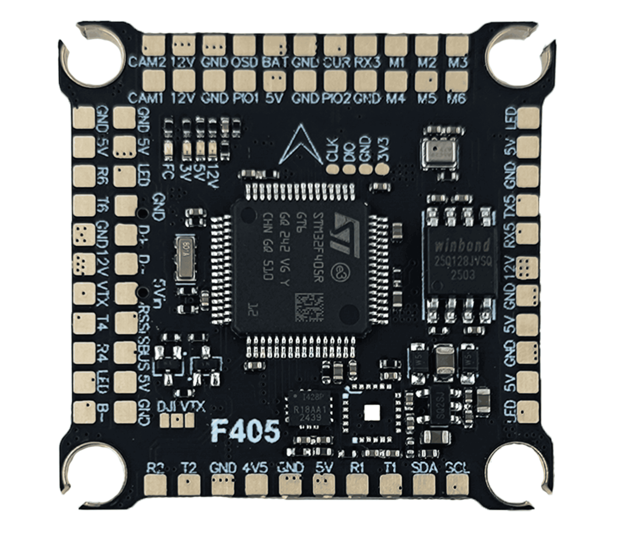
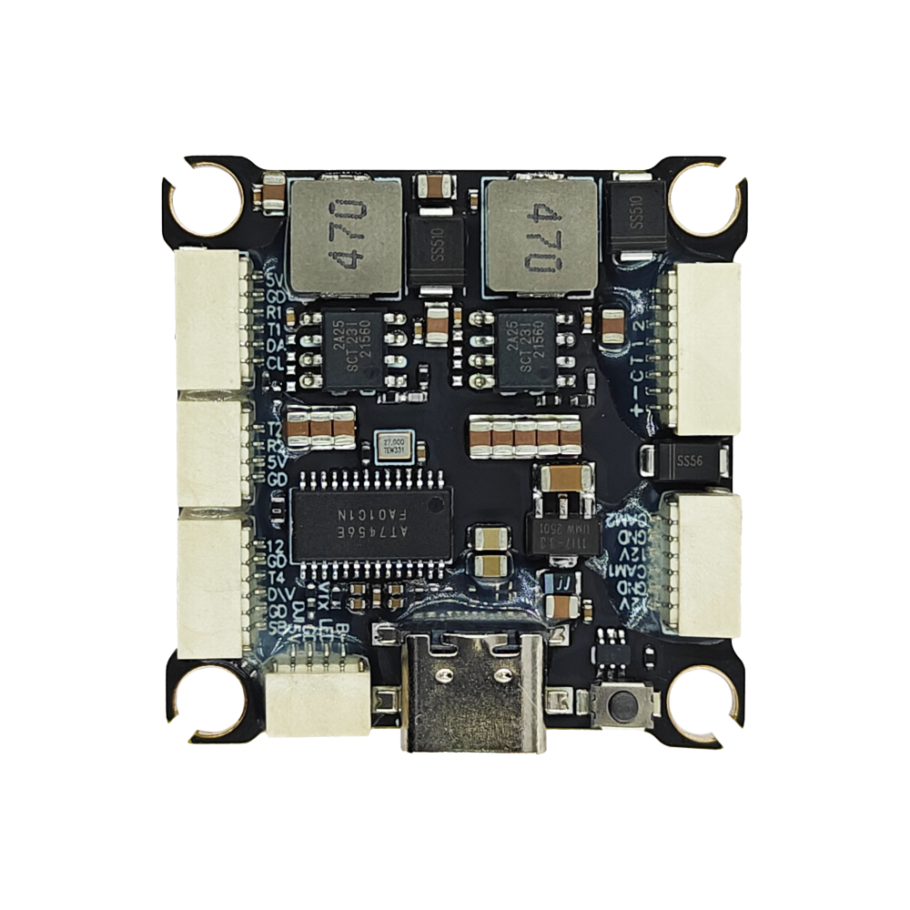
Pinout
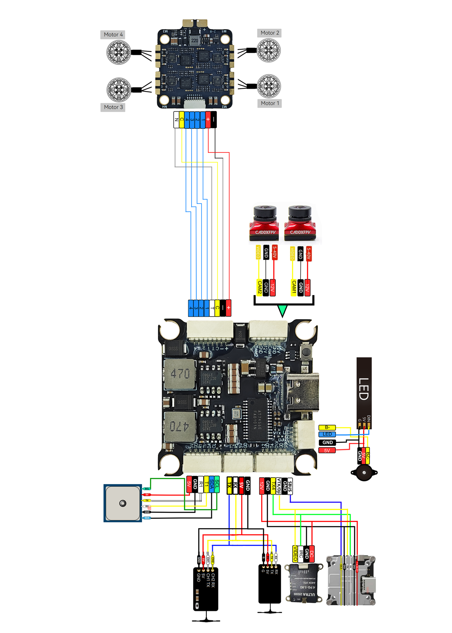
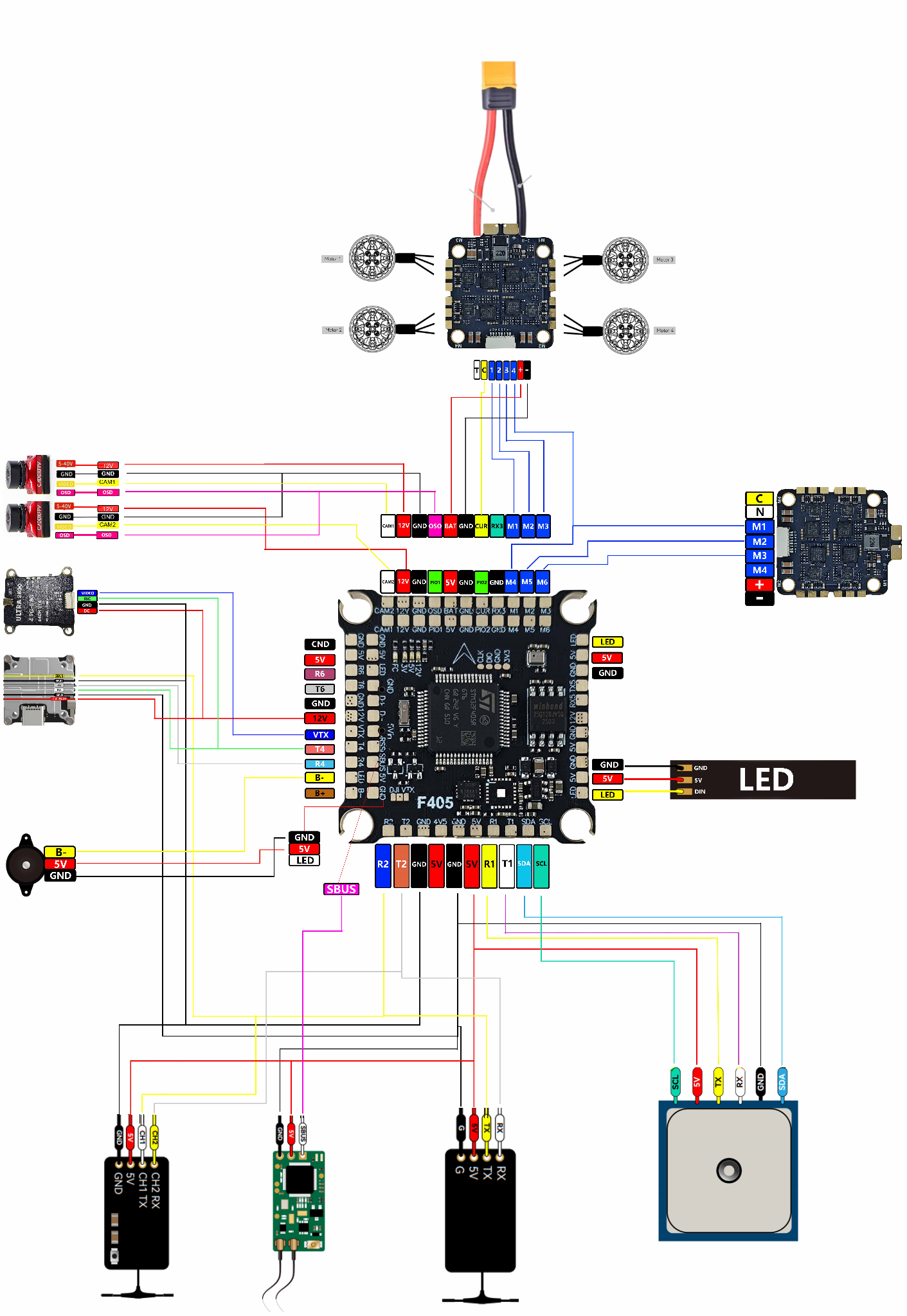
Typical Wiring Diagram
UART Mapping
The UARTs are marked Rn and Tn in the above pinouts. The Rn pin is the receive pin for UARTn. The Tn pin is the transmit pin for UARTn.
SERIAL0 -> USB
SERIAL1 -> UART1 (GPS) DMA capable
SERIAL2 -> UART2 (RCin) RX DMA capable
SERIAL3 -> UART3 (ESC Telemetry) DMA capable
SERIAL4 -> UART4 (DisplayPort) TX DMA capable
SERIAL5 -> UART5 (User)
SERIAL6 -> UART6 (User)
RC Input
RC input is configured by default via the USART2 RX input. It supports all unidirectional serial RC protocols except PPM and SBUS. The SBUS pin is inverted and applied to R2 for SBUS support.
FPort requires an external bi-directional inverter attached to T2 and SERIAL2_OPTIONS set to 4 (half-duplex). See FPort Receivers.
CRSF/ELRS uses RX2/TX2.
SRXL2 requires a connection to T2 and automatically provides telemetry. Set SERIAL2_OPTIONS to “4”.
PWM Output
The DAKEFPV F405 supports up to 7 PWM or DShot outputs. The pads for motor output M1 to M6 are provided on both the motor connectors and on separate pads.
The PWM is in 4 groups:
PWM 1-2 in group1
PWM 3-4 in group2
PWM 5-6 in group3
PWM 7(LED) in group4 (set as Serial LED output function by default)
Channels within the same group need to use the same output rate. If any channel in a group uses DShot then all channels in the group need to use DShot.
Battery Monitoring
The board has a built-in voltage sensor and external current sensor input. The current sensor can read up to 130 Amps. The voltage sensor can handle up to 8S LiPo batteries.
The correct battery setting parameters are:
BATT_VOLT_MULT 11.0
BATT_AMP_PERVLT 83.3
RSSI
ADC Pin 12 -> Analog RSSI voltage monitoring. Set RSSI_TYPE = 1 and RSSI_ANA_PIN = 12. For RSSI embedded in digital RC protocols like CRSF, set RSSI_TYPE = 3
Compass
The DAKEFPV F405 does not have a builtin compass, but you can attach an external compass using I2C on the SDA and SCL pads.
OSD Support
The autopilot has an onboard OSD using a MAX7456 chip and is enabled by default. The CAM1/2 and VTX pins provide connections for using the internal OSD. Simultaneous DisplayPort OSD is also possible and is configured by default.
VTX power control
GPIO 81 controls the VTX BEC output to pins marked “12V”. Setting this GPIO low removes voltage supply to pins. By default RELAY2 is configured to control this pin and sets the GPIO high on boot.
Camera control
GPIO 82 controls the camera output to the connectors marked “CAM1” and “CAM2”. Setting this GPIO low switches the video output from CAM1 to CAM2. By default RELAY3 is configured to control this pin and sets the GPIO high on boot.
Loading Firmware
Firmware for these boards can be found here in sub-folders labeled “DAKEFPVF405”.
Initial firmware load can be done with DFU by plugging in USB with the bootloader button pressed. Then you should load the “with_bl.hex” firmware, using your favourite DFU loading tool.
Once the initial firmware is loaded you can update the firmware using any ArduPilot ground station software. Updates should be done with the *.apj firmware files.