Sky-Drones AIRLink Overview
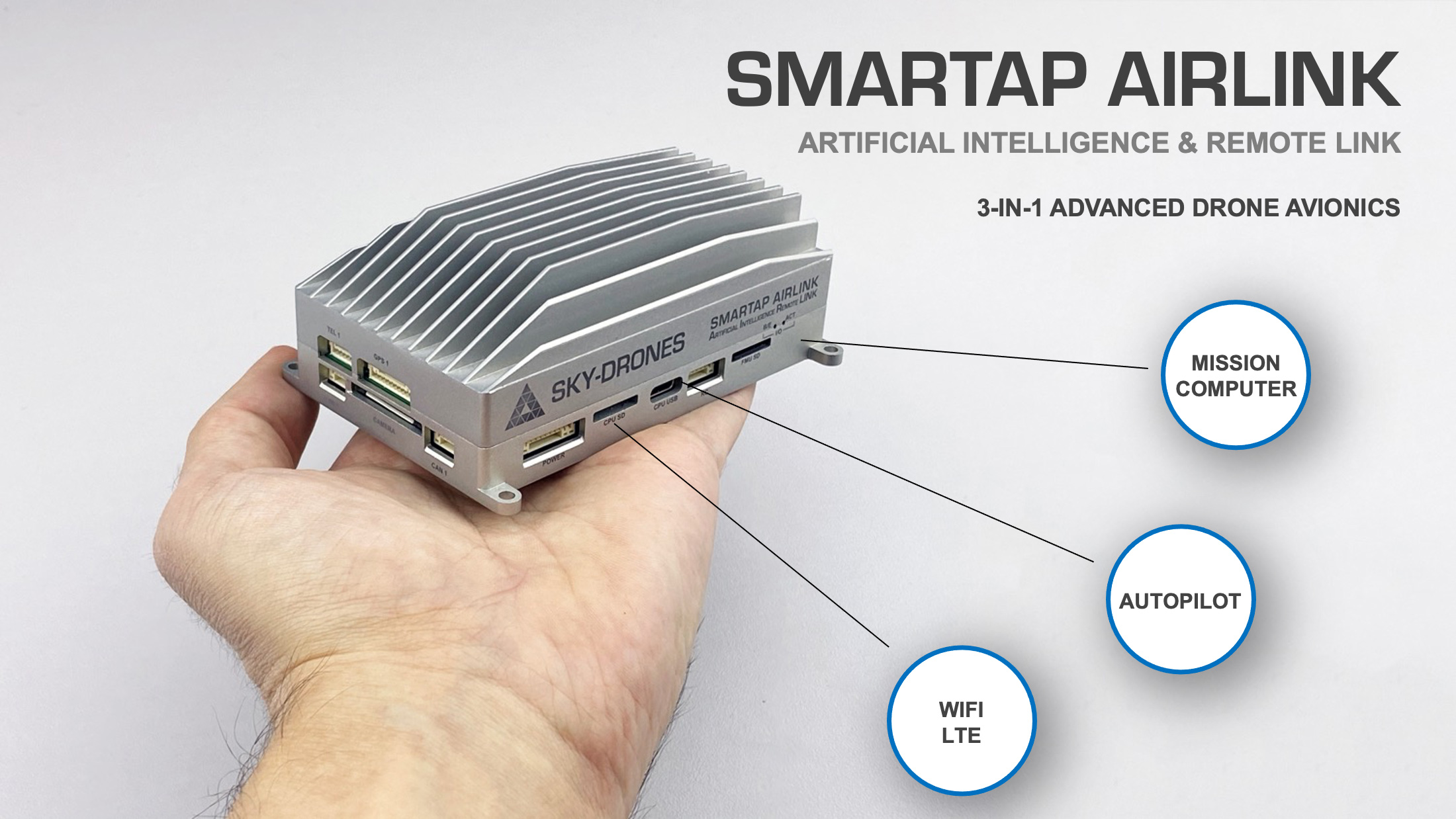
AIRLink stands for Artificial Intelligence & Remote Link. The unit includes a cutting-edge drone autopilot, AI mission computer and LTE connectivity unit. AIRLink helps to reduce the time to market for new drone manufacturers from years and months down to weeks.
System Features
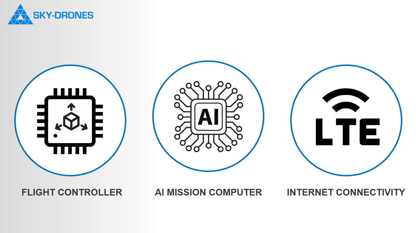
SmartAP AIRLink has two computers and integrated LTE Module:
The flight control computer (autopilot) has a triple-redundant vibration-dampened and temperature-stabilized IMU.
The powerful AI mission computer enables advanced drone software features like computer vision and obstacle avoidance, digital HD video streaming, and payload data streaming.
LTE and WiFi connectivity modules provide permanent broadband internet connection which is enabler for remote workflows.
Feature highlights
Specifications
Sensors
3x Accelerometers, 3x Gyroscopes, 3x Magnetometers, 3x Pressure sensorss
GNSS, Rangefinders, Lidars, Optical Flow, Cameras
3x-redundant IMU
Vibration dampening
Temperature stabilization
Flight Controller
STM32F7, ARM Cortex M7 with FPU, 216 MHz, 2MB Flash, 512 kB RAM
STM32F1, I/O co-processor
Ethernet, 10/100 Mbps
LAN with AI Mission Computer
8x UARTs: Telemetry 1, Telemetry 2 (AI Mission Computer), Telemetry 3, GPS 1, GPS 2, Extra UART, Serial Debug Console, IO
2x CAN: CAN1, CAN2
USB with MAVLink
Serial console for debugging
RC Input, SBUS input, RSSI input, PPM input
16x PWM servo outputs (8 from IO, 8 from FMU)
3x I2C ports
High-powered piezo buzzer driver
High-power RGB LED
Safety switch / LED option
AI Mission Computer
6-Core CPU: Dual-Core Cortex-A72 + Quad-Core Cortex-A53
GPU Mali-T864, OpenGL ES1.1/2.0/3.0/3.1
VPU with 4K VP8/9, 4K 10bits H265/H264 60fps Decoding
Remote power control, software reset, power down, RTC Wake-Up, sleep mode
RAM Dual-Channel 4GB LPDDR4
16GB eMMC
MicroSD up to 256GB
Ethernet 10/100/1000 Native Gigabit
WiFi 802.11a/b/g/n/ac, Bluetooth
USB 3.0 Type C
2x Video: 4-Lane MIPI CSI (FPV Camera) and 4-Lane MIPI CSI with HDMI Input (Payload Camera)
LTE Connectivity Module
4G LTE UMTS/HSPA(+), GSM/GPRS/EDGE
1x External slot, 1x Integrated eSIM
LTE Antenna, 2x2 MIMO
Bands: Europe, North America, Australia, Japan, Other
Set content
SmartAP AIRLink set includes everything needed to setup the system and get prepared for the flight. Standard set contains:
1x AIRLink Enterprise unit
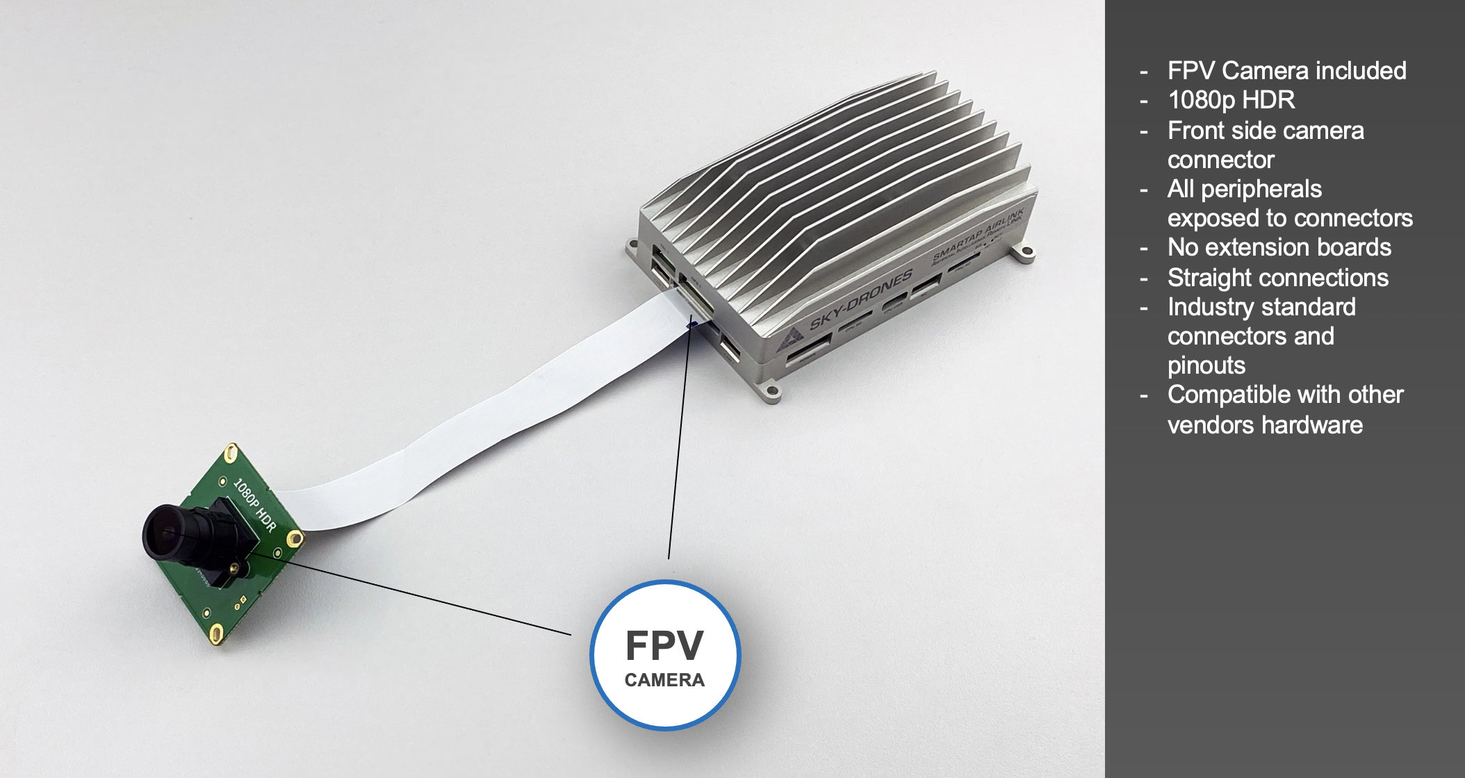
1x FPV camera with CSI cable
1x WiFi antenna with MMCX connector
2x LTE antenna with MMCX connector
1x HDMI to mini HDMI cable1x set of cables (7 cables for all connectors)
AIRLink Telemetry based on the Microhard LAN/IP-based RF micromodule is available as an add-on and is fully compatible with AIRLink.
Editions
AIRLink editions offer different integration levels required by drone manufacturers: Enterprise and Core. AIRLink Enterprise is ideal for a quick start, evaluation and prototyping while Core is optimised for deep integration and mid-high volume manufacturing.
AIRLink Enterprise
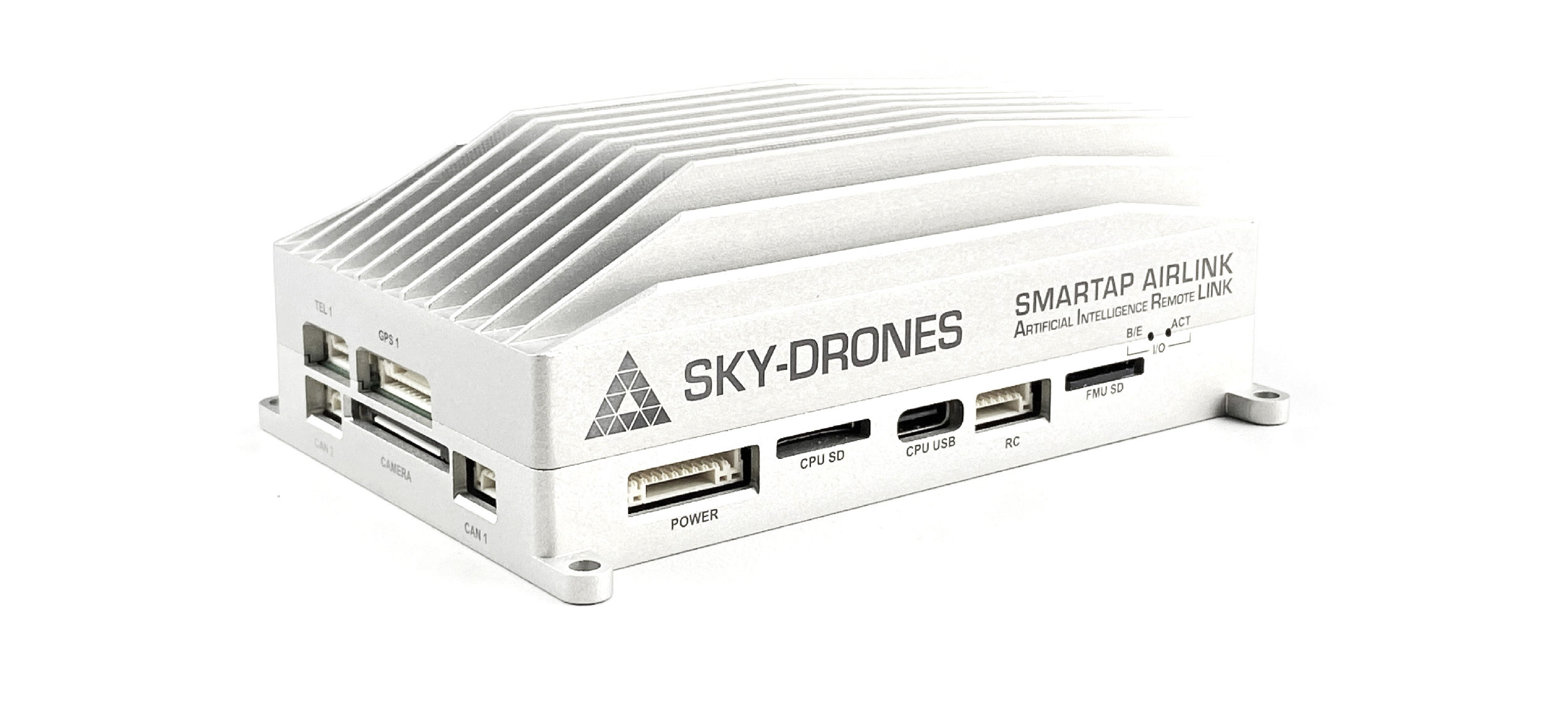
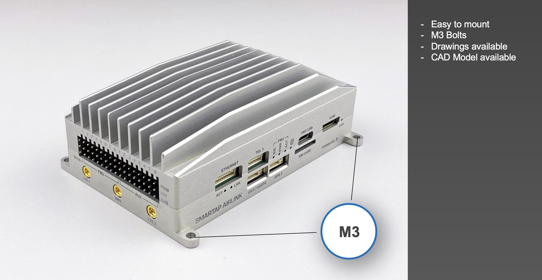
SmartAP AIRLink’s Enterprise edition is intended for prototyping and low to medium volume drone production. Quick and easy installation thanks to the dedicated mounting holes and integrated heatsink for power dissipation.
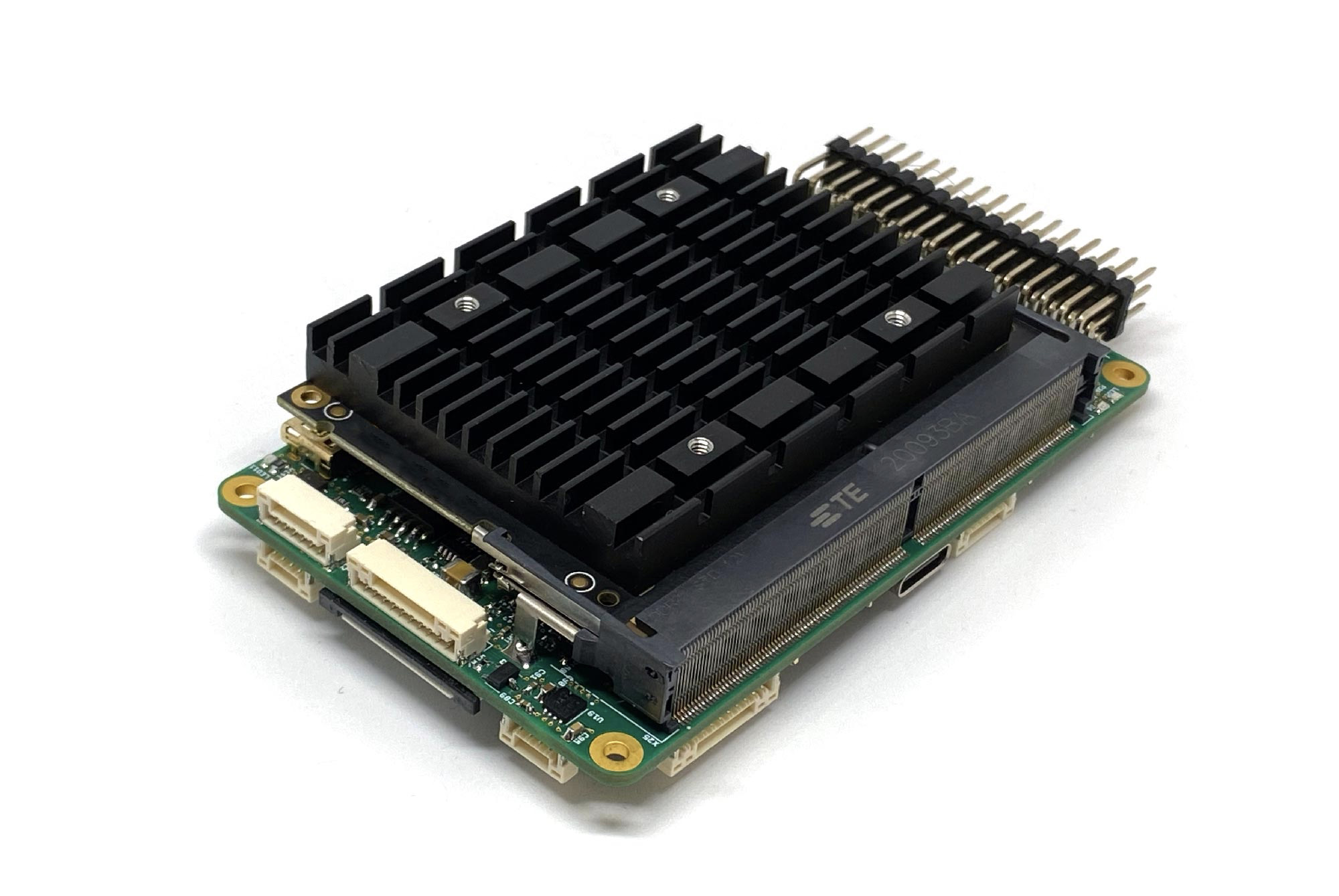
AIRLink Core
SmartAP AIRLink’s Core edition is intended for medium to high volume production and deep integration with customer’s hardware. It weighs only 89 g and can be attached to a metal frame for optimum cooling.
| Parameter | AIRLink Enterprise | AIRLink Core |
|---|---|---|
| Enclosure | Aluminum, with integrated heatsink and fan mounting option. | External heatsink or reasonable power dissipation should be provided by the design. |
| Dimensions | L103 x W61 x H37 mm | L100 x W57 x H22 mm |
| Weight | 198 g | 89 g |
| Ambient temperature | -40°C-..+50°C | -40°C-..+50°C |
Features
Easy to mount
FPV camera comes as standard
Interfaces
Left side
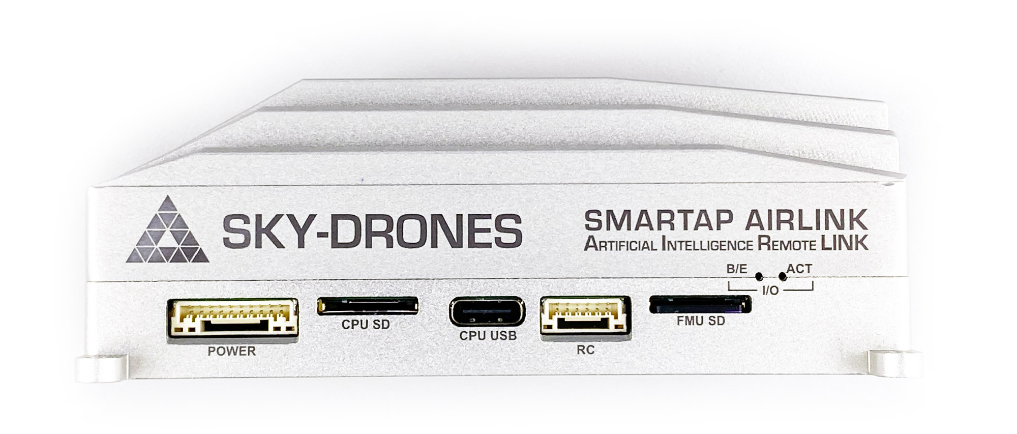
Left side interfaces:
Power input with voltage & current monitoring
AI Mission Computer micro SD card
Flight Controller micro SD card
AI Mission Computer USB Type-C
PPM input, SBUS output, RSSI monitor
POWER - JST GH SM10B-GHS-TB
| Pin number | Pin name | Direction | Voltage | Function |
|---|---|---|---|---|
| 1 | 12V | IN | +12V | Main power input |
| 2 | 12V | IN | +12V | Main power input |
| 3 | 12V | IN | +12V | Main power input |
| 4 | BAT_CURRENT | IN | +3.3V | Battery current monitoring |
| 5 | BAT_VOLTAGE | IN | +3.3V | Battery voltage monitoring |
| 6 | 3V3 | OUT | +3.3V | 3.3V output |
| 7 | PWR_KEY | IN | +3.3V | Power key input |
| 8 | GND | Ground | ||
| 9 | GND | Ground | ||
| 10 | GND | Ground |
CPU SD card - microSD
CPU USB - USB Type C
RC Connector - JST GH SM06B-GHS-TB
| Pin number | Pin name | Direction | Voltage | Function |
|---|---|---|---|---|
| 1 | 5V | OUT | +5V | 5V output |
| 2 | PPM_IN | IN | +3.3V | PPM input |
| 3 | RSSI_IN | IN | +3.3V | RSSI input |
| 4 | FAN_OUT | OUT | +5V | Fan output |
| 5 | SBUS_OUT | OUT | +3.3V | SBUS output |
| 6 | GND | Ground |
FMU SD card - microSD
Right side
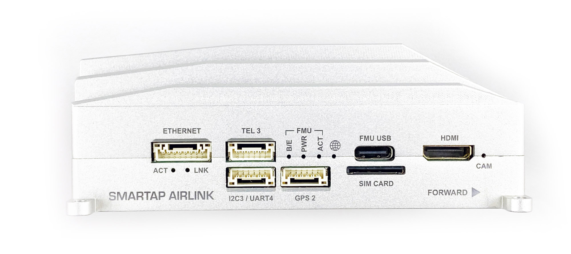
Right side interfaces:
Ethernet port with power output
Telemetry port
Second GPS port
Spare I2C / UART port
Flight controller USB Type-C
Micro SIM Card
HDMI input port (payload camera)
ETHERNET - JST GH SM08B-GHS-TB
| Pin number | Pin name | Direction | Voltage | Function |
|---|---|---|---|---|
| 1 | 5V | OUT | +5V | Radio module power supply |
| 2 | 5V | OUT | +5V | Radio module power supply |
| 3 | ETH_TXP | OUT | +3.3V | Ethernet transmit positive |
| 4 | ETH_TXN | OUT | +3.3V | Ethernet transmit negative |
| 5 | ETH_RXP | IN | +3.3V | Ethernet receive positive |
| 6 | ETH_RXN | IN | +3.3V | Ethernet receive negative |
| 7 | GND | Ground | ||
| 8 | GND | Ground |
TEL3 - JST GH SM06B-GHS-TB
| Pin number | Pin name | Direction | Voltage | Function |
|---|---|---|---|---|
| 1 | 5V | OUT | +5V | Power supply output |
| 2 | USART2_TX | OUT | +3.3V | Telemetry 3 TX |
| 3 | USART2_RX | IN | +3.3V | Telemetry 3 RX |
| 4 | USART2_CTS | IN | +3.3V | Telemetry 3 CTS |
| 5 | USART2_RTS | OUT | +3.3V | Telemetry 3 RTS |
| 6 | GND | Ground |
I2C3 / UART4 - JST GH SM06B-GHS-TB
| Pin number | Pin name | Direction | Voltage | Function |
|---|---|---|---|---|
| 1 | 5V | OUT | +5V | Power supply output |
| 2 | USART4_TX | OUT | +3.3V | UART 4 TX |
| 3 | USART4_RX | IN | +3.3V | UART 4 RX |
| 4 | I2C3_SCL | I/O | +3.3V | I2C3 Clock |
| 5 | I2C3_SDA | I/O | +3.3V | I2C3 Data |
| 6 | GND | Ground |
GPS2 - JST GH SM06B-GHS-TB
| Pin number | Pin name | Direction | Voltage | Function |
|---|---|---|---|---|
| 1 | 5V | OUT | +5V | Power supply output |
| 2 | USART8_TX | OUT | +3.3V | UART 8 TX |
| 3 | USART8_RX | IN | +3.3V | UART 8 RX |
| 4 | I2C2_SCL | I/O | +3.3V | I2C2 Clock |
| 5 | I2C2_SDA | I/O | +3.3V | I2C2 Data |
| 6 | GND | Ground |
FMU USB - USB Type C
SIM Card - micro SIM
HDMI - mini HDMI
Front side
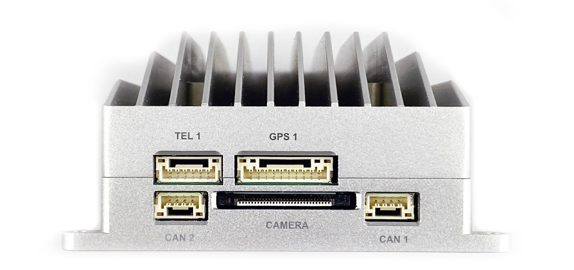
Front side interfaces:
Main GNSS and compass port
Main telemetry port
CSI camera input
CAN 1
CAN 2
TEL1 - JST GH SM06B-GHS-TB
| Pin number | Pin name | Direction | Voltage | Function |
|---|---|---|---|---|
| 1 | 5V | OUT | +5V | Power supply output |
| 2 | USART7_TX | OUT | +3.3V | Telemetry 1 TX |
| 3 | USART7_RX | IN | +3.3V | Telemetry 1 RX |
| 4 | USART7_CTS | IN | +3.3V | Telemetry 1 CTS |
| 5 | USART7_RTS | OUT | +3.3V | Telemetry 1 RTS |
| 6 | GND | Ground |
GPS1 - JST GH SM10B-GHS-TB
| Pin number | Pin name | Direction | Voltage | Function |
|---|---|---|---|---|
| 1 | 5V | OUT | +5V | Power supply output |
| 2 | USART1_TX | OUT | +3.3V | GPS 1 TX |
| 3 | USART1_RX | IN | +3.3V | GPS 1 RX |
| 4 | I2C1_SCL | I/O | +3.3V | Mag 1 Clock |
| 5 | I2C1_SDA | I/O | +3.3V | Mag 1 Data |
| 6 | SAFETY_BTN | IN | +3.3V | Safety button |
| 7 | SAFETY_LED | OUT | +3.3V | Safety LED |
| 8 | +3V3 | OUT | +3.3V | 3.3V output |
| 9 | BUZZER | OUT | +5V | Buzzer output |
| 10 | GND | Ground |
CAN1 - JST GH SM04B-GHS-TB
| Pin number | Pin name | Direction | Voltage | Function |
|---|---|---|---|---|
| 1 | 5V | OUT | +5V | Power supply output |
| 2 | CAN1_H | I/O | +5V | CAN 1 High (120Ω) |
| 3 | CAN1_L | I/O | +5V | CAN 1 Low (120Ω) |
| 4 | GND | Ground |
CAN2 - JST GH SM04B-GHS-TB
| Pin number | Pin name | Direction | Voltage | Function |
|---|---|---|---|---|
| 1 | 5V | OUT | +5V | Power supply output |
| 2 | CAN2_H | I/O | +5V | CAN 2 High (120Ω) |
| 3 | CAN2_L | I/O | +5V | CAN 2 Low (120Ω) |
| 4 | GND | Ground |
CAMERA - FPC 30 pin, 0.5mm pitch
Rear side
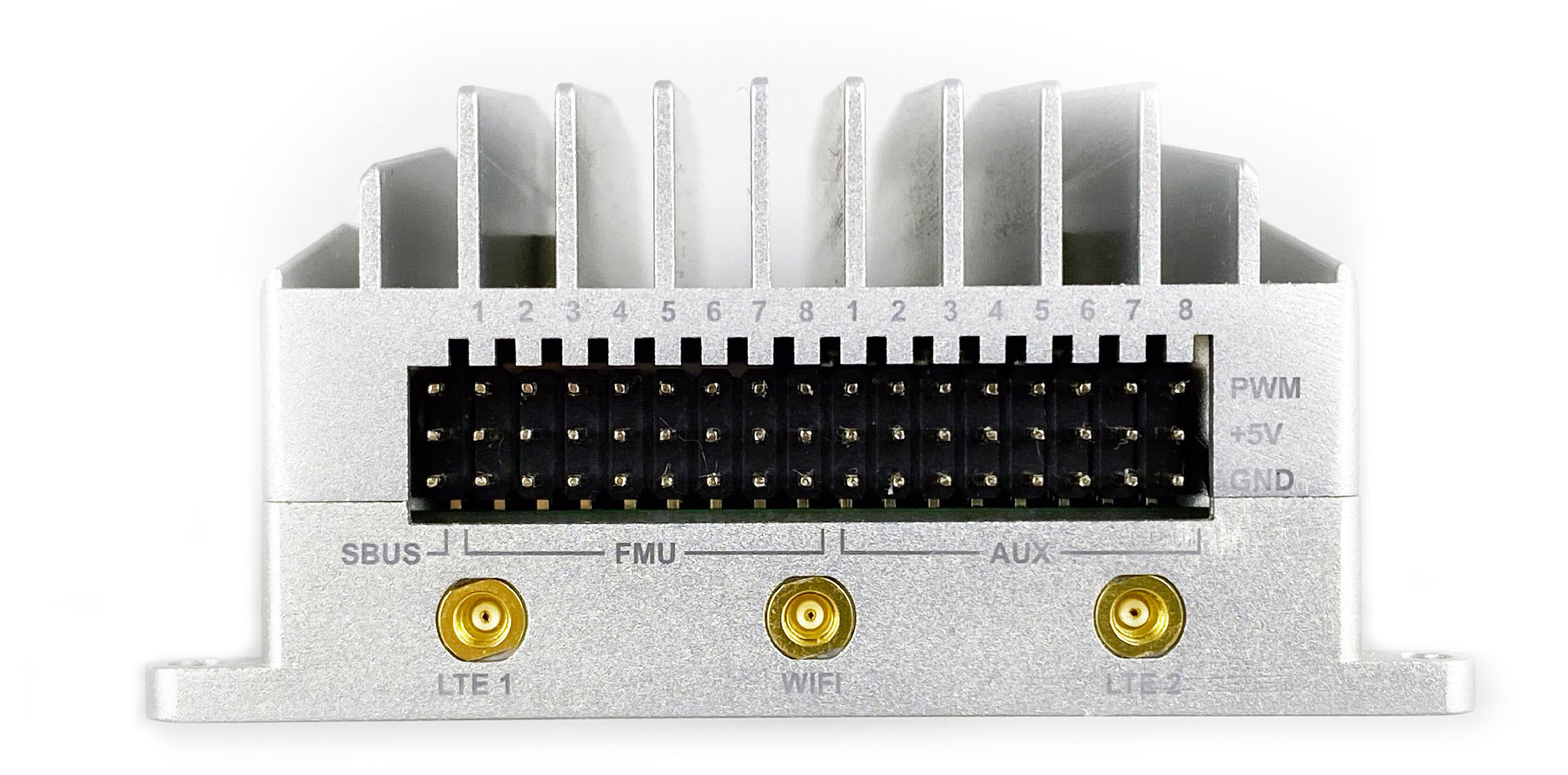
Rear side interfaces:
SBUS input
16 PWM output channels
2x LTE antenna sockets (MIMO)
WiFi antenna socket (AP & Station modes)
UART Order
AIRLink has a large number of internal and external serial ports:
| Serial | UART | Function |
|---|---|---|
| Serial 0 | USB | Console |
| Serial 1 | UART 7 | Telemetry 1 |
| Serial 2 | UART 5 | Telemetry 2 (used internally with Mission Computer) |
| Serial 3 | USART 1 | GPS 1 |
| Serial 4 | UART 8 | GPS 2 |
| Serial 5 | USART 3 | Debug console (internal connector) |
| Serial 6 | USART 2 | Telemetry 3 |
| Serial 7 | UART 4 | External UART |
RC Input
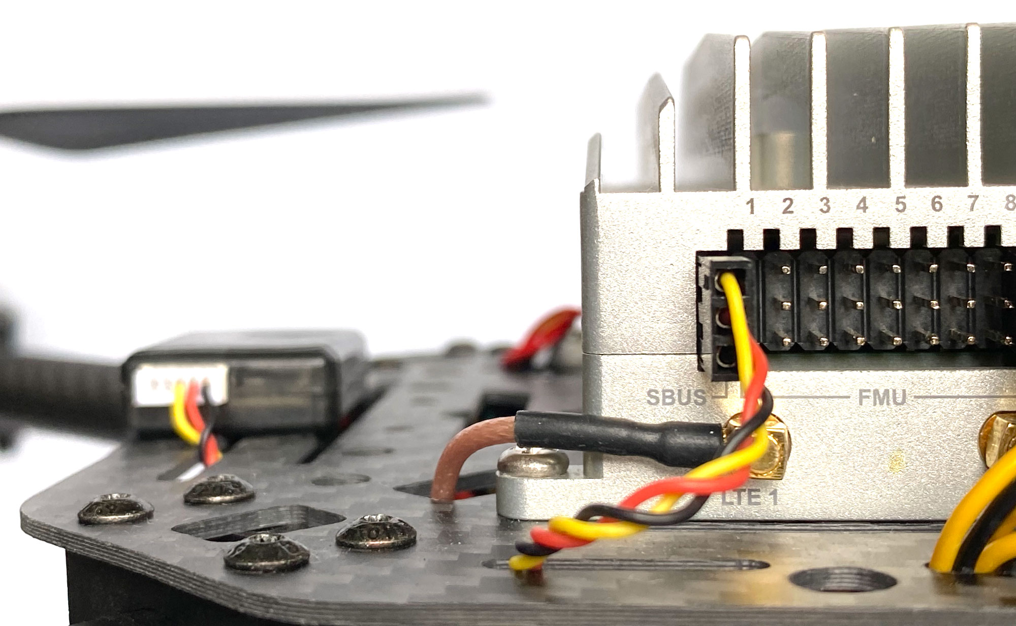
RC input is configured on the SBUS pin and is connected to IO MCU via an inverter internally. For PPM receivers please use RC Connector PPM pin located on the left side of the unit.
Outputs
AIRLink has 16 PWM outputs. Main outputs 1-8 and connected to IO MCU. AUX outputs 1-8 are connected to FMU.
| Output | Timer | Channel |
|---|---|---|
| AUX 1 | Timer 1 | Channel 4 |
| AUX 2 | Timer 1 | Channel 3 |
| AUX 3 | Timer 1 | Channel 2 |
| AUX 4 | Timer 1 | Channel 1 |
| AUX 5 | Timer 4 | Channel 2 |
| AUX 6 | Timer 4 | Channel 3 |
| AUX 7 | Timer 12 | Channel 1 |
| AUX 8 | Timer 12 | Channel 2 |
DShot capability can be used on the first four AUX pins.
More Information
For more information and instructions on setting up and using the AIRLink system see AIRLink Documentation
For technical help, support and customization please get in touch at Sky-Drones contact page
More information can be found at www.sky-drones.com
Frequently asked questions are answered in FAQ
Reference design
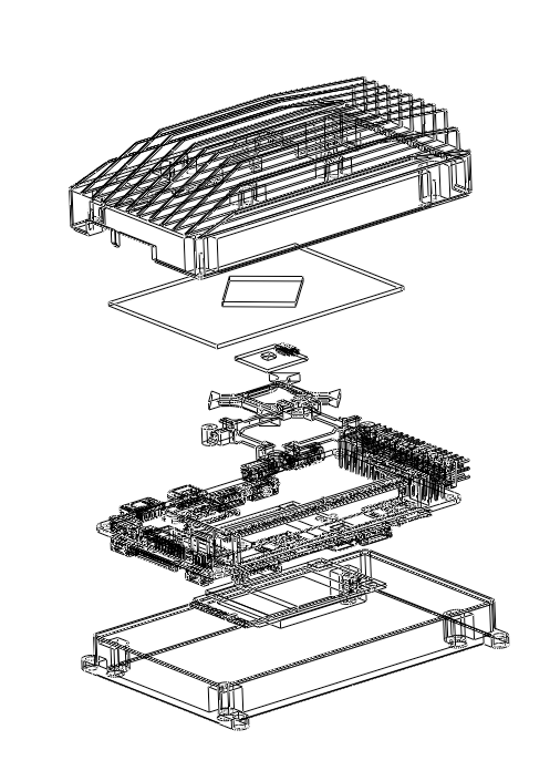
AIRLink CAD model is available here.
AIRLink Reference design can be provided by request. Get in touch at Sky-Drones contact page
Firmware
Firmware for AIRLink can be found here in sub-folders labeled “AIRLink”.
Where to Buy
Purchase from the original Sky-Drones Store here.
Worldwide shipping with 1-2 days order processing time
Distributors information coming soon