MSP OSD
ArduPilot supports several types of On Screen Displays (OSD) using MSP (MultiWii Serial Protocol) based protocols:
MSP Telemetry based OSDs such as DJI FPV Goggles V1/V2, DJI Goggles RE, FatShark ByteFrost, FatShark SharkByte (before fw 09042021), older MWOSD (newer versions support MAVLink, see Minim/MWOSD OSD Quick Installation Guide) , etc.
DisplayPort based OSDs such as HDZero (previously known as FatShark SharkByte (fw 09042021 and later)), Walksnail, DJI goggles using the wtf-os firmware and msdp-osd module, and MWOSD’s DisplayPort mode/firmware.
Telemetry only based OSDs will render OSD panel items on screen with their own engine based on the standard MSP telemetry sensor messages sent using Serial port protocol “32”, so ArduPilot has no control of how the items look.
DJI 2/V1/V2 goggles also have an extended protocol which is sent using Serial port protocol “33” that allows position information for each OSD panel when using their extended Custom OSD feature. This also allows the display of any ArduPilot OSD panel.
DisplayPort, on the other hand, is an MSP protocol extension that allows ArduPilot to specify text characters/icons and their positions to be drawn on external OSD displays like it does on internal integrated analog OSDs using Serial port protocol “42”. DisplayPort is also known (incorrectly) as CANVAS MODE. Basically it’s a remote text only frame buffer that uses local fonts (local to the rendering engine i.e. the OSD hardware) to render strings sent via MSP.
Telemetry based OSD
Telemetry based OSDs will render OSD panel items on screen with their own engine, so ArduPilot has no control of how the items look. Another limitation of telemetry based OSDs is that there’s no way for ArduPilot to add new panel items at will, it’s the vendor’s responsibility to add new features by rolling out new firmware releases.
If an on-board integrated analog OSD is present and the user wishes to have both OSDs , it can be activated as well. For example, on vehicles using the DJI goggles/air system for medium range, but still running a long range analog VTX using the internal OSD, for when the vehicle exceeds the range of the HD DJI Goggles. This configuration could use one OSD screen optimized for DJI Goggles, and another for the integrated OSD and the user can switch between them depending on which video system is being viewed.
Configuration
Example assumes connection of air unit to SERIAL2 of the flight controller.
OSD_TYPE = 3 if no integrated OSD is being used, or = 1 if an integrated OSD is present and the user wishes to have both OSDs.
SERIAL2_PROTOCOL = 32 (MSP)
SERIAL2_BAUD = 115
MSP_OPTIONS bit 0 = 0 (Do not EnableTelemetryMode) if the Air Unit is to be connected by both RX and TX input to the AutoPilot Serial port TX/RX. Set bit 0 = 1 (EnableTelemetryMode) if a standalone OSD unit connected only via a single wire from its RX input to the Serial ports’ TX. This is known as “push” mode.
OSD Panels Available with MSP telemetry OSDs
These are the MSP only OSD elements supported on telemetry based OSDs (assuming the OSD has the capability itself to display these telemetry values):
OSD Parameter |
Notes |
|---|---|
OSDn_ALTITUDE |
Home relative altitude |
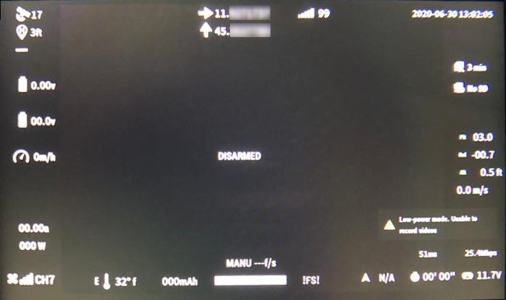
OSDn_ARMING |
Arming status, hidden when armed otherwise showing DISARMED |
OSDn_ASPEED |
Please refer to OSDn_GSPEED for more info on enabling airspeed display |
OSDn_BAT_VOLT |
First battery voltage |
OSDn_BATBAR |
First battery remaining percentage rendered as a bar based on declared capacity and consumed mAh |
OSDn_BATUSED |
First battery consumed mAh |
OSDn_CELLVOLT |
First battery average cell voltage, if automatic cell detection fails please override with MSP_OSD_NCELLS |
OSDn_CLK |
Realtime clock (requires GPX fix) |
OSDn_CRSSHAIR |
Artificial horizon is not supported so crosshair is often kept hidden |
OSDn_CURRENT |
First battery current |
OSDn_ESCTEMP |
On DJI V1/V2 Goggles this will report the highest ESC temperature |
OSDn_FLTMODE |
DJI hardware does not support ArduPilot’s flight modes! This item will generally be blank and only show !FS! while in failsafe! |
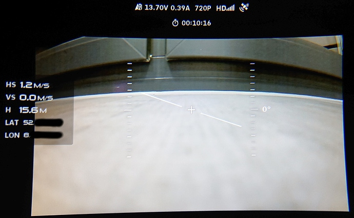
OSDn_GPSLAT |
GPS Latitude in decimal format |
OSDn_GPSLONG |
GPS Longitude in decimal format |
OSDn_GSPEED |
This item shows ground speed unless |
OSDn_HEADING |
Not supported by DJI V1/V2 Goggles |
OSDn_HOMEDIR |
Rotating arrow pointing to home |
OSDn_HOMEDIST |
Distance from home |
OSDn_HORIZON |
Not supported by DJI V1/V2 Goggles |
OSDn_MESSAGE |
This will display status text messages as rolling text. Status text messages will be hidden after a couple seconds and the panel will show the current flightmode. If |
OSDn_PITCH |
Pitch angle |
OSDn_POWER |
Instant power calculated as voltage * current |
OSDn_ROLL |
Roll angle |
OSDn_RSSI |
Rssi as configured in RSSI_TYPE: RSSI Type |
OSDn_SATS |
On DJI V1/V2 Goggles when there’s no telemetry based MSP OSDfix it will report 14 sats, this is a known DJI bug |
OSDn_SIDEBARS |
Not supported by DJI V1/V2 Goggles |
OSDn_VSPEED |
Vertical speed |
OSDn_WIND |
Please refer to OSDn_MESSAGE for wind speed and direction rendering |
DJI goggles in their default OSD display mode support MSP telemetry display with the following notes:
ArduPilot currently supports all of the OSD panel items provided by the V1 and V2 DJI FPV Goggles, as given in the table above .
Changing display units other than metric and imperial are not currently supported.
Multiple screens and remote switching of those screens is supported.
Displaying statistics on a dedicated screen is supported, see below for details.
Warning levels for RSSI, Voltage, etc. currently not supported
DJI V1 FPV Goggles
DJI Goggles RE
DJI 2/V1/V2 Goggles without the WTFOS modifications
In addition to native MSP telemetry only based OSD display, a “Custom OSD” facility was added in later models that allows any or all the OSD information panels provided by ArduPilot, and warnings, units, etc. to be displayed and positioned.
Configuration
To enable this, set the following parameters (example using SERIAL port 2 as the port to attach to the DJI Air unit using both TX and RX lines):
OSD_TYPE = 3 if no integrated OSD is being used in order to activate the OSD code. If an integrated OSD is present and the user wishes to have both OSDs , then OSD_TYPE = 1 will activate the on-board OSD as well as providing screens for the MSP OSD function. For example, on vehicles using the DJI goggles/air system for medium range, but still running a long range VTX using the internal OSD for when the vehicle exceeds the range of the HD DJI Goggles. This configuration could use one OSD screen optimized for DJI Goggles, and another for the integrated OSD and the user can switch between them depending on which video system is being viewed.
SERIAL2_PROTOCOL = 33 (DJI FPV)
SERIAL2_BAUD = 115
MSP_OPTIONS bit 0 = 0 (Do not EnableTelemetryMode)
MSP_OPTIONS bit 2 = 1 (EnableBTFLFonts) forces ArduPilot to impersonate Betaflight and use a Betaflight compatible font index for the font table integrated in the remote OSD system. This is required since the goggles do not have an ArduPilot compatible fonts table.
OSD_OPTIONS bit 5 = 1 (TranslateArrows) use corrected direction arrows when using the Betaflight fonts.
Note
Serial port baud rate default is changed to 115.2Kbaud automatically when setting the above protocol type. However, if the user has previously or subsequently changes the baud, this default will not be used. 115.2Kbaud is required by most video goggle systems.
Note
DJI Custom OSD must be enabled: in SETTINGS->DISPLAY->CUSTOM OSD menu of goggles.
Using Mission Planner to Configure the Layout
Mission Planner(MP) has a tab in its CONFIG menu to configure the on-board OSD many autopilots integrate, as well as setup layouts for Displayport OSDs. This same configuration tab can be used to configure the OSD panels.
Note
Mission Planners’ OSD setup screen now supports HD OSD configuration. To enable it check “HD Layout” in Editor Options at the top right of the OSD screen you want to change.
You can change the MSP OSD display configuration by connecting Mission Planner to SITL while the MSP OSD emulation window is active. By doing this, you can adjust and tweak your OSD configuration using SITL without having to worry about overheating your VTX. Once you are done you can take the OSD parameters you have settled on and move them to your vehicle.
Mission Planner can be connected running on the same computer, or networked computer, to MAVProxy, using this command in MAVProxy:
output add <ip address of box running Mission Planner>:14550
Note
if MP is running on the same PC, the ip address would be 127.0.0.1 (local host address)
For more information about using Mission Planner with SITL Please refer to the onboard OSD with SITL documentation