BROTHERHOBBYF405v3
The BROTHERHOBBYF405v3 is a flight controller produced by BROTHERHOBBY.
Features
STM32F405 microcontroller
ICM42688P IMU
SPL06 barometer
AT7456E OSD
10V 2A BEC; 5V 2A BEC
16Mb Onboard Flash
6 UARTs
8 PWM outputs
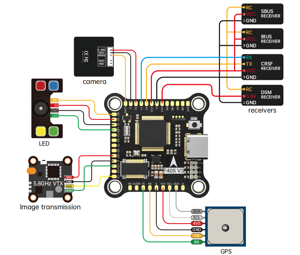
Pinout
UART Mapping
Default protocols and serial port mapping
SERIAL0 -> USB (MAVLink2)
SERIAL1 -> UART1 (RX1 only and is inverted from SBUS pin in HD VTX connector)
SERIAL2 -> UART2 (RX, DMA-enabled)
SERIAL3 -> UART3 (DJI)
SERIAL4 -> UART4 (USER)
SERIAL5 -> UART5 (ESC Telemetry)
SERIAL6 -> UART6 (GPS)
RC Input
The default RC input is configured on UART2, and all ArduPilot compatible protocols, except PPM and SBUS, are supported. SBUS support is provided via the HD VTX connector on SERIAL1 and but requires the protocol be set to SERIAL1_PROTOCOL = “23” and to change SERIAL2_PROTOCOL to something other than ‘23’.
PPM is not supported
FPort requires an external bi-directional inverter (see FPort Receivers)
CRSF requires connection to TX2 and automatically supports telemetry
DSM/SRXL connects to the RX2 pin, but SBUS would still be connected to SBUS.
SRXL2 requires a connection to TX2 and automatically provides telemetry. Set SERIAL2_OPTIONS to “4”.
FrSky Telemetry
FrSky Telemetry can be supported using a spare UART’s transmit pin. For example, you could set the following parameters to enable support for FrSky S.PORT on SERIAL4
OSD Support
The BROTHERHOBBYF405v3 supports OSD using OSD_TYPE 1 (MAX7456 driver). Simultaneously, DisplayPort HD VTX connections can be made to UART3 (included on the HD VTX connector).
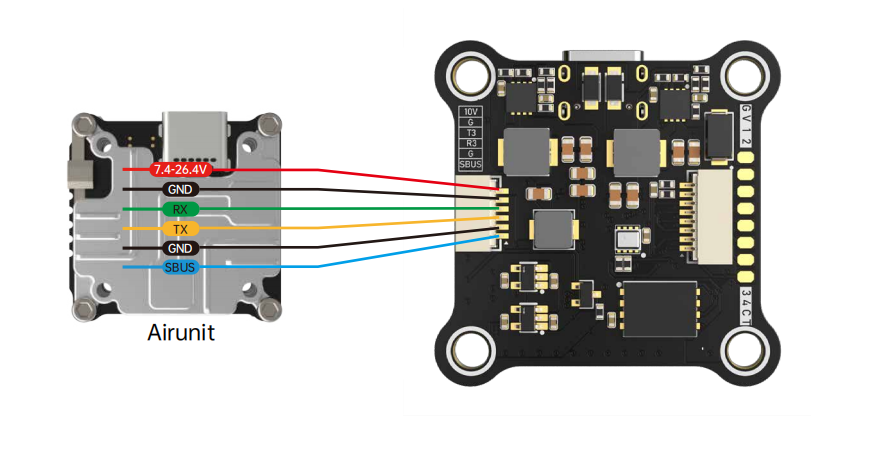
VTX Support
The SH1.0-6P connector supports a standard DJI HD VTX connection. Pin 1 of the connector is 10v so be careful not to connect anything that could be damaged by this voltage.
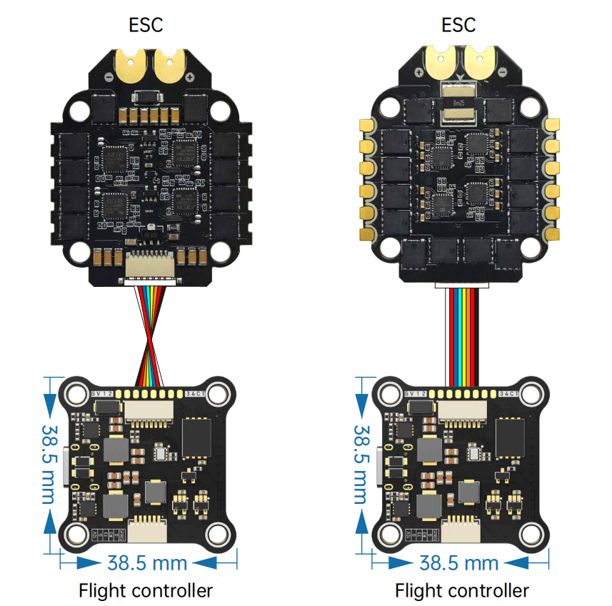
PWM Outputs
The BROTHERHOBBYF405v3 supports up to 9 PWM outputs. Outputs 1-4 are on the ESC connector, while the others are available via solder pads.
Channels 1-8 support DShot. Channels 1-4 support bi-directional DShot.
PWM outputs are grouped into 5 groups and every group must use the same output protocol:
PWM 1-2 in group1
PWM 3-4 in group2
PWM 5-6 in group3
PWM 7-8 in group4
PWM 9 in group5 (LED pad)
Battery Monitoring
The board has a internal voltage sensor and connections on the ESC connector for an external current sensor input. The voltage sensor can handle up to 6S LiPo batteries.
The default battery parameters are:
BATT_MONITOR = 4
BATT_VOLT_PIN = 10
BATT_CURR_PIN = 11
BATT_VOLT_MULT = 11
BATT_AMP_PERVLT = 25.9 (will need to be adjusted for whichever current sensor is attached)
RSSI
ADC Pin 15 -> RSSI voltage monitoring
Compass
The BROTHERHOBBYF405v3 does not have a built-in compass, but you can attach an external compass using I2C on the SDA and SCL connector.
Firmware
Firmware for the BROTHERHOBBYF405v3 can be found here in sub-folders labeled “BROTHERHOBBYF405v3”.
Loading Firmware
Initial firmware load can be done with DFU by plugging in USB with the bootloader button pressed. Then you should load the “with_bl.hex” firmware, using your favorite DFU loading tool.
Once the initial firmware is loaded you can update the firmware using any ArduPilot ground station software. Updates should be done with the “*.apj” firmware files.