BROTHER HOBBY H743
The BROTHERHOBBYH743 is a flight controller produced by BROTHERHOBBY.
Features
STM32H743 microcontroller
Dual ICM42688P IMU
SPL06 barometer
AT7456E OSD
12V 3A BEC; 5V 3A BEC
SDCard
7 UARTs
13 PWM outputs
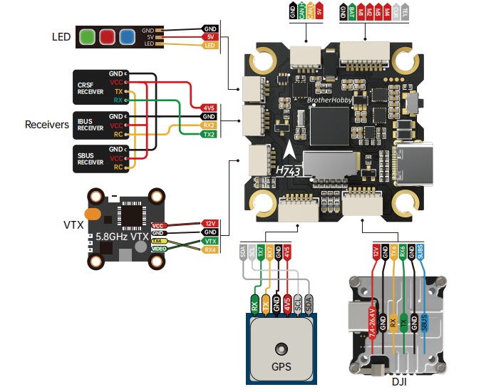
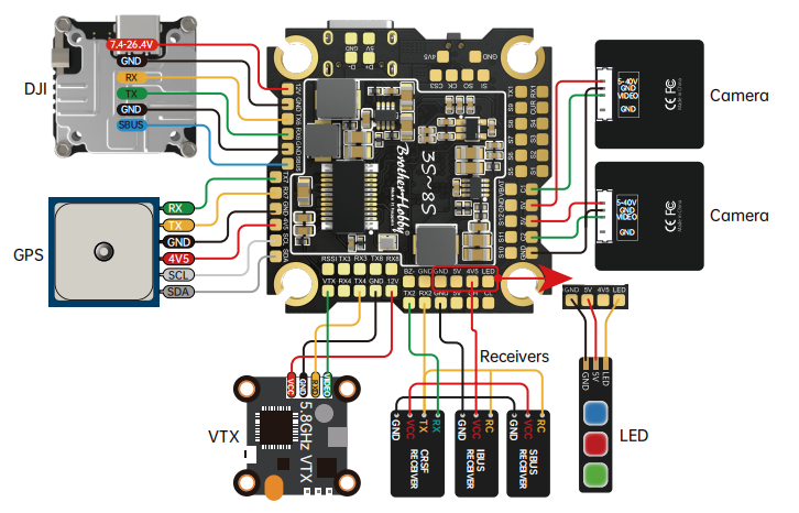
Pinout
UART Mapping
SERIAL0 -> USB
SERIAL1 -> UART1 (ESC Telemetry)
SERIAL2 -> UART2 (RX/SBUS, DMA-enabled)
SERIAL3 -> UART3 (Spare, DMA-enabled)
SERIAL4 -> UART4 (Spare)
SERIAL6 -> UART6 (DJI, DMA-enabled)
SERIAL7 -> UART7 (GPS, DMA-enabled)
SERIAL8 -> UART8 (Spare)
RC Input
The default RC input is configured on the UART2_RX inverted from the SBUS pin. All unidirectional ArduPilot compatible protocols, except PPM, are supported. Receivers using bi-directional protocols such as CRSF/ELRS should be tied to the TX2 and RX2 pins.
FPort requires connection to TX2 . See FPort Receivers.
CRSF/ELRS also requires a TX2 connection, in addition to RX2, and automatically provides telemetry.
SRXL2 requires a connection to TX2 and automatically provides telemetry. Set SERIAL2_OPTIONS to “4”.
FrSky Telemetry
FrSky Telemetry can be supported using any UART. For example, the T4 pin (UART4 transmit). You need to set the following parameters to enable support for FrSky S.PORT
OSD Support
The BROTHERHOBBYH743 supports using its internal OSD (MAX7456 driver). Simultaneous DisplayPort OSD operation is also pre-configured on SERIAL 6. See MSP OSD for more info.
VTX Support
The SH1.0-6P connector supports a standard DJI HD VTX connection. Pin 1 of the connector is 12v so be careful not to connect to devices that cannot accept that voltage.
PWM Output
The BROTHERHOBBYH743 supports up to 13 PWM outputs. All outputs except 11/12 support DShot. Outputs 1-8 support bi-directional DShot.
PWM outputs are grouped and every group must use the same output protocol:
PWM 1-2 in group1
PWM 3-4 in group2
PWM 5-6 in group3
PWM 7-10 in group4
PWM 11-12 in group5
PWM 13 in group6 - LED strip
Battery Monitoring
The board has a internal voltage sensor and connections on the ESC connector for an external current sensor input. The voltage sensor can handle up to 6S LiPo batteries.
The default battery parameters are:
BATT_MONITOR = 4
BATT_VOLT_PIN = 10
BATT_CURR_PIN = 11
BATT_VOLT_MULT = 11
BATT_AMP_PERVLT = 40.2
RSSI
ADC Pin 8 -> RSSI voltage monitoring
Compass
The BROTHERHOBBYH743 does not have a built-in compass, but you can attach an external compass using I2C on the SDA and SCL connector.
VTX power control
GPIO 81 controls the VTX BEC output to pins marked “10V”. Setting this GPIO low removes voltage supply to pins. By default RELAY2 is configured to control this pin and sets the GPIO high.
Camera control
GPIO 82 controls the camera output to the connectors marked “CAM1” and “CAM2”. Setting this GPIO high switches the video output from CAM1 to CAM2. By default RELAY3 is configured to control this pin and sets the GPIO low.
Loading Firmware
Initial firmware load can be done with DFU by plugging in USB with the bootloader button pressed. Then you should load the “with_bl.hex” firmware, using your favorite DFU loading tool.
Once the initial firmware is loaded you can update the firmware using any ArduPilot ground station software. Updates should be done with the “*.apj” firmware files.
Firmware for these boards can be found at https://firmware.ardupilot.org in sub-folders labeled “BROTHEHOBBYH743”.