GPIOs
In order to use an output as a GPIO, the individual SERVOx_FUNCTION parameter is merely set to “-1”. If set to “0”, it remains a PWM output, unassigned to a function, but will not output any PWM signal unless commanded by scripting or a GCS.
Note
If the servo function is being “mirrored” to a remote device, as in the case of a DroneCAN or KDECAN ESC, then in order to change the autopilot board’s corresponding output pin to be a GPIO, but allow the SERVOx_FUNCTION to still be assigned to the remote device, the SERVO_GPIO_MASK parameter can be used to assign the board pin to be a GPIO without affecting the SERVOx_FUNCTION assignment for the remote device.
Warning
GPIOs should only source or sink 8mA (20mA absolute maximum). They are intended as logic-level IO and must not be used to directly drive relay coils, motors, LED strings, etc. Directly connecting electromechanical or high-current devices to GPIOs can permanently damage the autopilot.
General Purpose Input/Outputs (GPIOs) are used in ArduPilot for control of relays, actuators, LEDs, camera triggers, Start Button etc. Some functions also use a GPIO pin as an input, like RPM Measurement. Some autopilots provide dedicated GPIO pins (sometimes labeled “CAPTURE” pins). In addition, GPIOs can be obtained by re-configuring the PWM outputs.
Configuring GPIOS
In order to set a PWM/SERVO/MOTOR output to be a GPIO function, the individual SERVOx_FUNCTION parameter is set to “-1”.
Note
for autopilots using IOMCUs, if a “MAIN” output is configured as a GPIO, it can only function as an output (ie RELAY,etc.) not an input. “AUX” outputs can function either as inputs or outputs when configures as a GPIO.
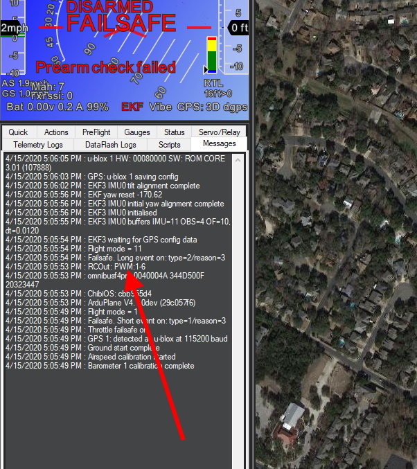
Every time the autopilot initializes, it sends a log message to the ground control station, showing which outputs are PWM/Oneshot/or DShot.
GPIO “PIN” NUMBER
Some GPIO-based functions require that the GPIO “pin number” to be entered into an associated parameter. This pin number is assigned in the autopilot’s hardware definition file. Usually, the first GPIO capable output is assigned pin 50, the second 51, etc. So in the above case of the Pixhawk, AUX OUT 6 is pin 55.
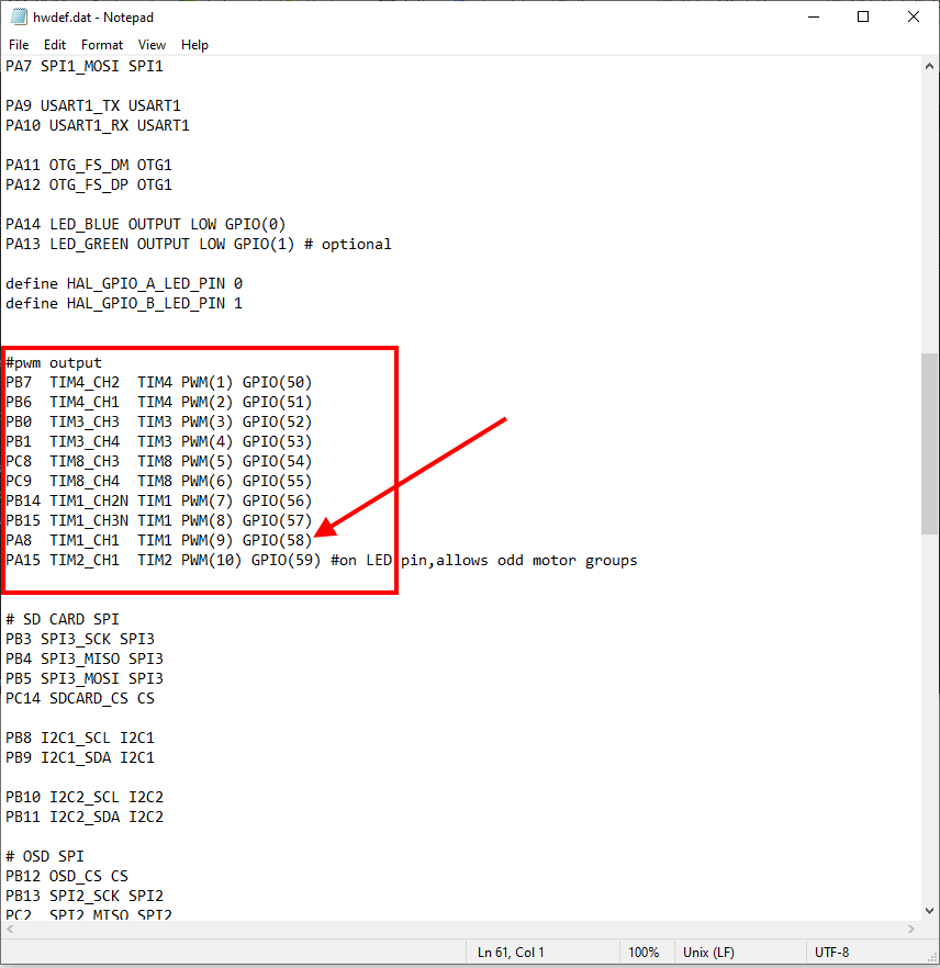
You can verify an output’s GPIO pin number assignment easily. First, find its hwdef.dat file here and determine the GPIO pin number listed beside its output number, as shown below:
IOMCU “MAIN” output 1 thru 8 are mapped to GPIO pin numbers 101 to 108, respectively.
Note
Usually, changing any feature or function’s GPIO pin assignment will require a reboot for it to take effect.