CoreWing F405 Wing V2 / Wing Mini V2
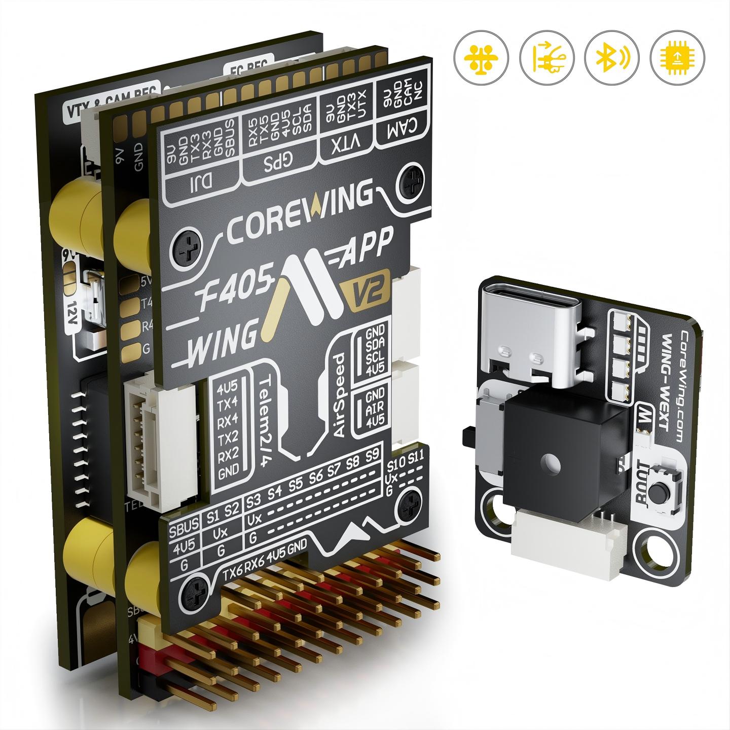
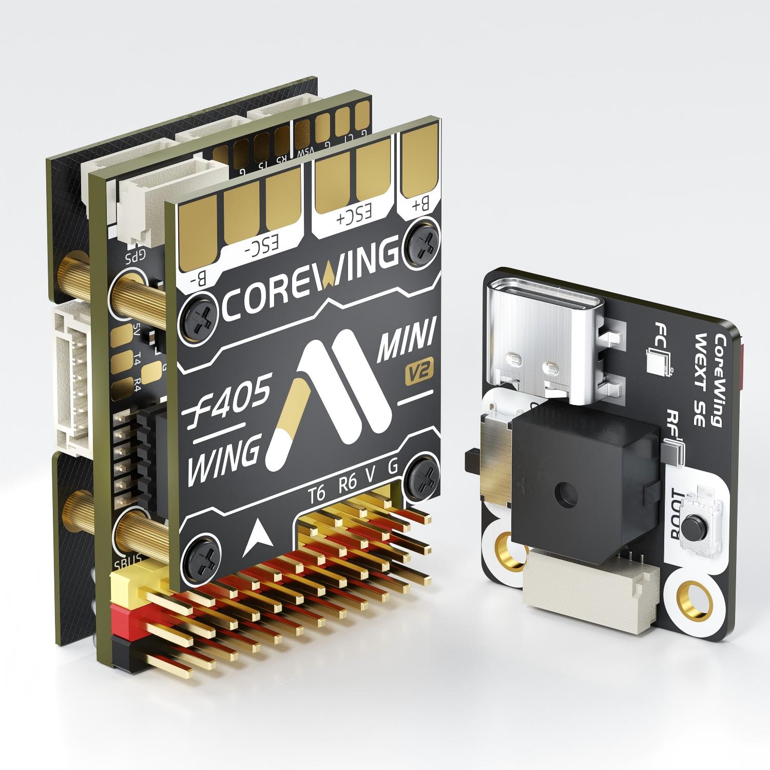
The CoreWing F405 Wing V2 and CoreWing F405 Wing Mini V2 are compact ArduPilot Plane flight controllers for fixed-wing and QuadPlane/VTOL aircraft, designed to simplify wiring, setup, and field configuration through integrated power, video/OSD, peripheral, and wireless features.
12 servo / motor outputs for conventional fixed-wing and QuadPlane configurations
Integrated PDB with servo / VTX power and voltage / current monitoring
Integrated AT7456 analog OSD, with a dedicated HD VTX interface
GPS, telemetry, RC receiver, compass, airspeed, and rangefinder ports
Included wireless module with BLE/Wi-Fi support for CoreWing app and Mission Planner connection
Note
Due to flash memory limitations, this board does not include all ArduPilot features. See Firmware Limitations for details.
Specifications
Processor
STM32F405RGT6 ARM, 168MHz
AT7456E OSD
ESP-S3 on Wing V2 / ESP8685 on Mini V2 for BLE/WiFi Telemetry
Sensors
ICM-42688P or BMI270 IMU, depending on board variant
SPA06-003 barometer
Voltage and current sensors
Power Input
Wing V2: 3S to 6S LiPo input, 10 V to 28 V
Mini V2: 2S to 6S LiPo input, 7 V to 28 V
90 A continuous / 215 A peak current sensing
Power Outputs
Board |
Typical Use |
Voltage |
Current(cont/peak) |
|---|---|---|---|
WingV2 |
Peripherals |
5.2V |
4A / 5A |
Servos |
5V, 6V, or 7.2V |
8A / 14A |
|
VTX/CAM |
5V,9V or 12V |
2A / 3A |
|
MiniV2 |
Peripherals |
5V |
2A / 3A |
Servos |
5V or 6V |
4A / 5A |
|
VTX/CAM |
|
1.5A / 2A |
Interfaces
12x PWM outputs
10x DShot-capable outputs and 2x standard PWM outputs
1x SBUS/PPM input
Dedicated serial RC input for CRSF/ELRS/TBS Crossfire
6x UARTs for GPS, telemetry, RC, display, VTX, and other peripherals, UART1 internally tied to Wireless board
1x I2C port for external compass, digital airspeed, and other I2C peripherals
4x ADC inputs: voltage, current, RSSI, analog airspeed, VB2 and CU2
Analog airspeed input
microSD card slot
USB-C port
Onboard BLE / WiFi wireless board
Switchable VTX supply
Size and Dimensions
Wing V2 : 52 mm x 32 mm x 17 mm, 40 g
Wing Mini V2 : 37 mm x 26 mm x 14 mm, 19 g
Where to Buy
User Manual
Wiring Diagram
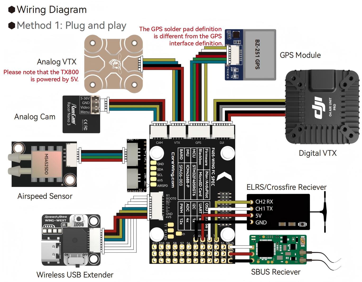
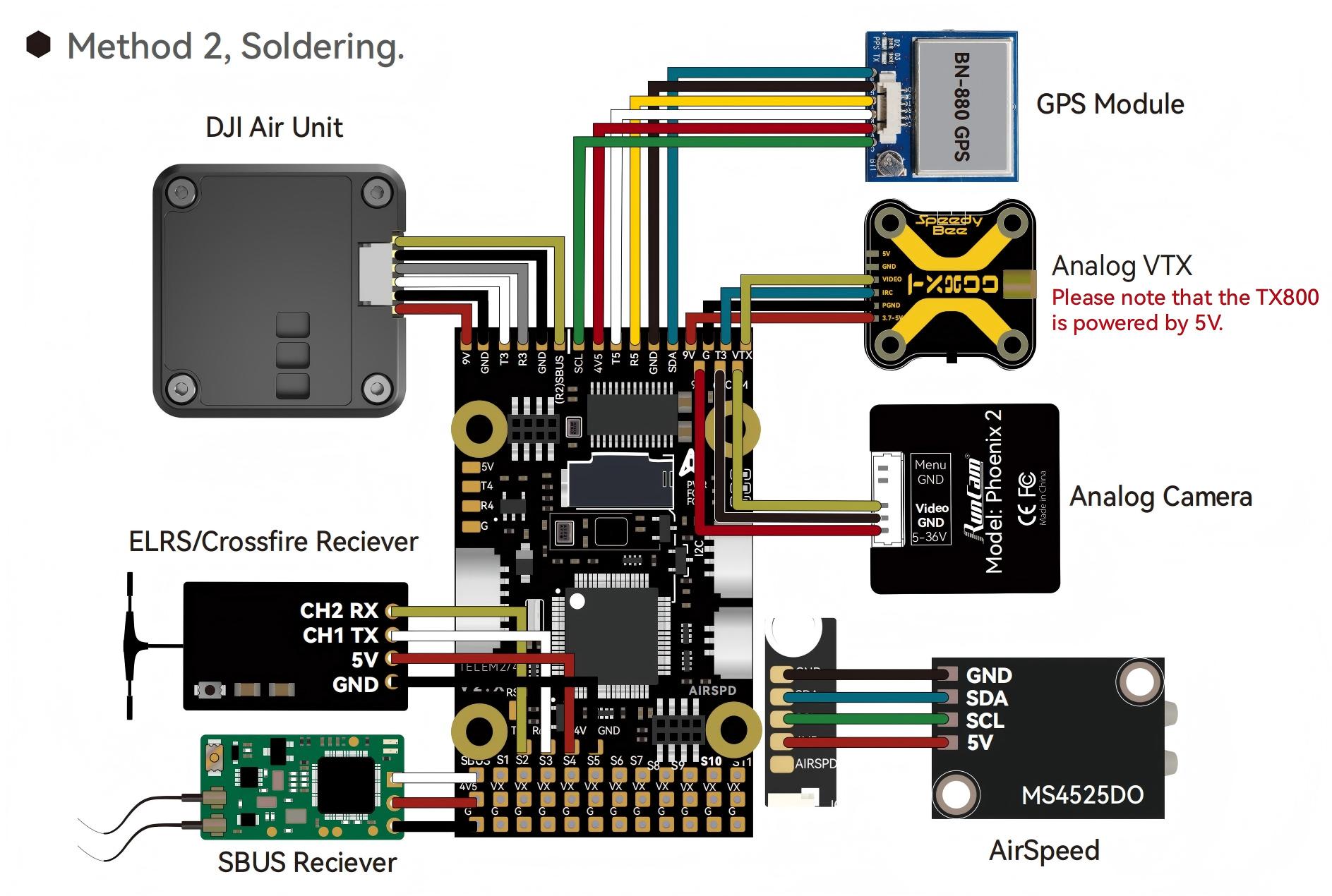
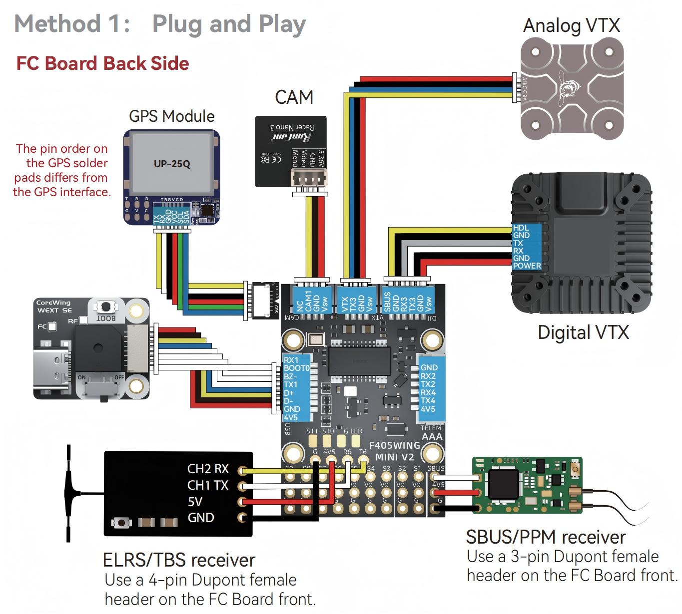
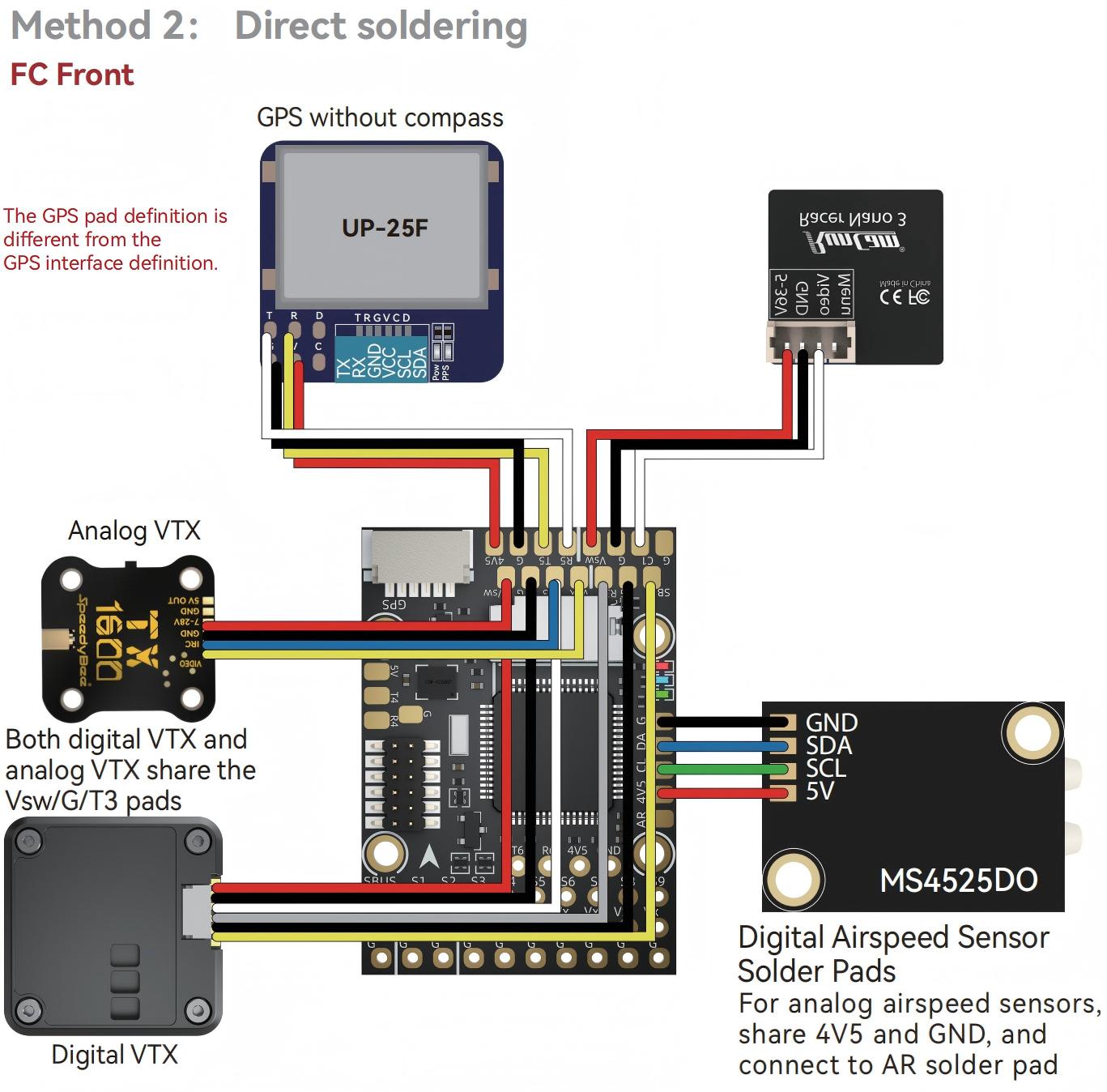
Default UART order
The UARTs are marked Rn and Tn in the above pinouts. The Rn pin is the receive pin for UARTn. The Tn pin is the transmit pin for UARTn.
SERIAL0 = console = USB
SERIAL1 = MAVLink2 = USART1, tied to the wireless module, DMA capable
SERIAL2 = USER = USART2, RX tied to inverted SBUS RC input, but can be used as normal UART if BRD_ALT_CONFIG =1
SERIAL3 = USER = USART3, available on DJI air unit connector, TX DMA capable
SERIAL4 = USER = UART4, TX DMA capable
SERIAL5 = GPS = UART5, available on GPS connector, TX DMA capable
SERIAL6 = RCIN = USART6, Serial RC input, DMA capable
Serial protocols shown are defaults, but can be adjusted to personal preferences.
RC Input
The SBUS input is passed through an inverter to RX2 (UART2 RX). By default, RX2 is mapped to a timer input instead of the UART and can be used for SBUS, PPM, and other receiver protocols that do not require a true UART.
Serial receiver protocols such as CRSF, ELRS, MAVLink RC input, and SRXL2 should be connected to UART6 using the TX6 and RX6 pins. SERIAL6_PROTOCOL is set to 23 by default for serial RC input.
Recommended receiver connections:
PPM: connect to the SBUS input
SBUS: connect to the SBUS input
CRSF / TBS Crossfire: connect to TX6 and RX6
- ELRS: connect to TX6 and RX6, same as CRSF. Set bit 13 of
RC_OPTIONS if required
DSM / SRXL: connect to RX6.
SRXL2: connect to TX6 and set SERIAL6_OPTIONS to 4.
FPort: connect to TX6 and RX6 through a bidirectional inverter. See FPort Receivers.
Note
UART6 is configured by default for serial receivers. You can also have more than one receiver in the system at a time (usually used for long range hand-offs to a remote TX). See Multiple Radio Control Receivers for details.
Any UART can be used for RC system connections in ArduPilot also, and is compatible with all protocols except PPM (SBUS requires external inversion on other UARTs). See Radio Control Systems for details.
Note
the “4V5” pin above the SBUS pin and the 4V5 pins in the GPS, Airspeed, and Telem connectors are powered when USB is connected. Be careful not to present too much load to the USB source or voltage droop may occur. All other 5V pins are only powered when battery is present.
Servo/Motor Outputs
All motor/servo outputs are PWM capable. PWM outputs 1 to 10 are also DShot capable. On the Wing V2, PWM outputs 1 to 4 additionally support bi-directional DShot; the Wing Mini V2 does not support bi-directional DShot. However, mixing DShot, serial LED, and normal PWM operation for outputs is restricted into groups, i.e. enabling DShot for an output in a group requires that all DShot-capable outputs in that group be configured and used as DShot, rather than PWM outputs.
PWM 1,2 in group 1 (TIM4)
PWM 3,4 in group 2 (TIM3)
PWM 5-7 in group 3 (TIM8)
PWM 8-10 in group 4 (TIM2)
PWM 11,12 in group 5 (TIM1)
Note
PWM 11 and PWM 12 only support normal PWM output. They do not support DShot.
Integrated PDB and Power Wiring
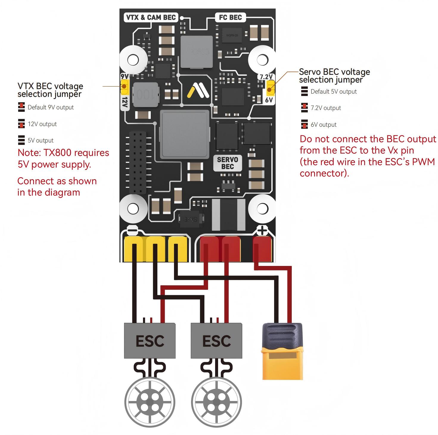
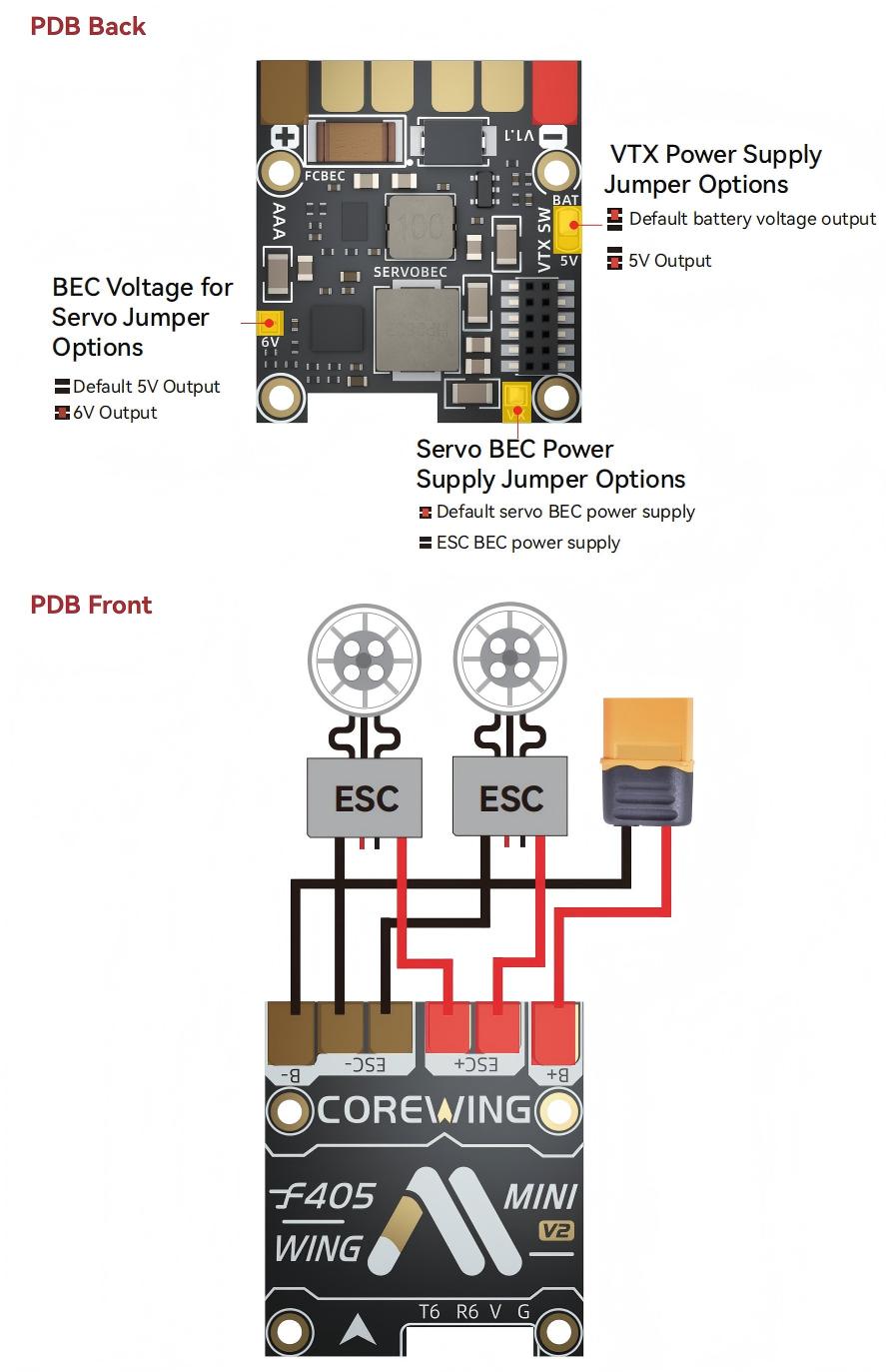
The board includes an integrated PDB with separate power rails for the flight controller/peripherals, servos, and VTX/camera equipment. This reduces the need for an external PDB or separate BEC modules in typical fixed-wing builds.
Wing V2 includes three onboard BECs: an FC BEC, a servo BEC, and a VTX/CAM BEC. Wing Mini V2 includes two onboard BECs: an FC BEC and a servo BEC. Its VTX/CAM power output is selectable between 5V and battery input, but it is not a separate third BEC.
CoreWing F405 Wing V2
CoreWing F405 Wing Mini V2
Note
On CoreWing F405 Wing Mini V2, if the VTX power output is set to battery voltage, make sure the connected camera or VTX supports the battery voltage.
Note
The servo rail is powered by the onboard servo BEC. Do not connect an ESC BEC red wire to the servo rail unless the board power jumper configuration allows an external BEC input.
Wireless Connection
The onboard CoreWing wireless board supports BLE and WiFi AP/STA modes. The CoreWing app can be used for wireless parameter setup, wireless firmware flashing, and wireless board settings. Mission Planner can connect through WiFi using TCP or UDP.
WiFi AP default settings:
SSID:
CoreWing WING-WiFiorCoreWing WING MINI-WiFiPassword:
88888888IP address:
192.168.1.1TCP port:
4278UDP port:
14550
In WiFi STA mode, connect using the IP address assigned by the router or hotspot.
OSD Support
The CoreWing F405 Wing V2 / Mini V2 supports using its internal OSD using OSD_TYPE 1 (MAX7456 driver). External OSD support such as DJI or DisplayPort is supported using UART3 or any other free UART. See MSP OSD for more info.
VTX Control
UART3 TX is located in the Video Output connector to provide IRC Tramp or Smart Audio control of video transmitters. See Video Transmitter Support for more information.
VTX Power Control
GPIO 81 controls the VTX/CAM power output. Setting this GPIO high removes voltage supply from the VTX/CAM power pins.
Set a RELAYx_PIN to 81 to control the switching. Then select an RC channel for control (Chx) and set its RCx_OPTION to the appropriate Relay (1-6) that you had set its pin parameter above.
For example, use Channel 7 to control the switch using Relay 1:
RELAY1_PIN = 81
RC7_OPTION = 28 (Relay1 Control)
Battery Monitor Settings
These should already be set by default. However, if lost or changed:
Enable Battery monitor with these parameter settings :
BATT_MONITOR = 4
Then reboot.
BATT_VOLT_PIN = 10
BATT_CURR_PIN = 11
BATT_VOLT_MULT = 11.05
BATT_AMP_PERVLT = 64 for Wing V2, or 51 for Wing Mini V2
Note
This autopilot uses a sensitive analog current sensor. ESC switching noise can affect current readings. A 35 V 470 uF electrolytic capacitor is included in the package and should be installed on the power input. In some cases, the ESCs themselves may need additional 200 uF to 470 uF low-ESR capacitors on their power inputs if they do not already include them.
Connecting a GPS/Compass module
These boards do not include a built-in GPS or compass module. An external GPS/compass module should be connected for autonomous modes that require position and heading information.
The GPS connector provides UART5, I2C, and 4V5 power. UART5 is GPS1 by default, and the I2C bus can be used for an external compass.
Note
The 4V5 pins are also powered when USB is connected. Avoid connecting high-current loads to 4V5 when powered only from USB.
Airspeed
The boards supports both analog and digital airspeed sensors.
Analog airspeed: use the AIR analog input, 0 V to 6.6 V range (ARSPD_PIN 15, set by default)
Digital airspeed: use the I2C airspeed connector
The MS4525DO, ASP5033, MS5525, SDP3X and NMEA digital airspeed sensors are enabled by default, in addition to analog airspeed. Other digital airspeed sensor drivers require a custom firmware build using the Custom Firmware Build Server.
Logging
The boards support microSD card logging.
Use a microSD card formatted as FAT16 or FAT32. SDSC and SDHC cards are recommended.
Firmware
Firmware for these boards can be found in the ArduPilot firmware server in sub-folders named:
CoreWingF405WingV2
CoreWingF405WMiniV2
These boards do not come with ArduPilot firmware pre-installed. Use the instructions here to load ArduPilot the first time:
Loading Firmware to Boards without an ArduPilot Compatible Bootloader
The CoreWing app can also be used for wireless firmware flashing after the wireless board is connected and configured.