JHEMCUF405PRO
(aka GHF405AIO-HD) Flight Controller
The JHEMCUF405PRO is an AIO flight controller produced by JHEMCU.
,.. note: There’s another version of the board that doesn’t have I2C pads exposed. This is not that one.
Features
MCU - STM32F405 32-bit processor running at 168 MHz
IMU - ICM42605
Barometer - DPS310
Voltage & current sensor
OSD - AT7456E
Onboard Flash: 8MB
5x UARTs (1,2,3,4,6)
5x PWM Outputs (4 Motor Output, 1 LED)
Battery input voltage: 2S-6S
BEC 5V/2.5A, 10V/2.0A
I2C: exposed pins
ESCs: BlheliS 40A (advertised)
LED strip: Supported
Buzzer: supported
Pinout
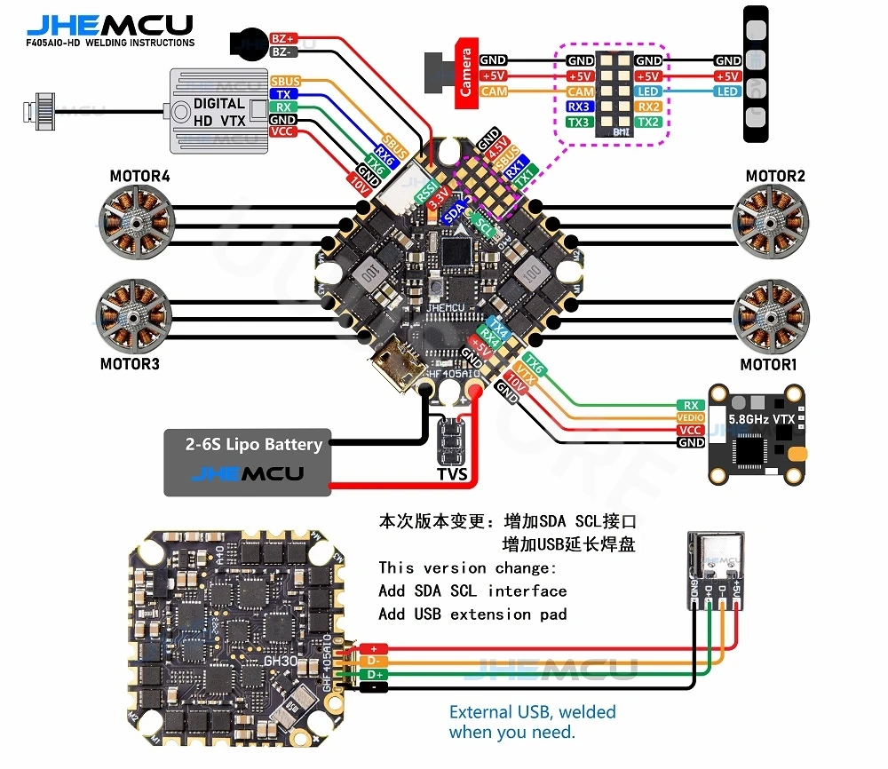
UART Mapping
The UARTs are marked RXn and TXn in the above pinouts. The RXn pin is the receive pin for UARTn. The TXn pin is the transmit pin for UARTn.
The board also has SH6P 1mm connector for digital FPV systems which has UART6.
Please note that the board will not enter DFU mode if the receiver is connected to either USART1/USART3/USART4). If you have it soldered there due to DMA requirements you will need to temporarily desolder the wire on the FC’s RX pad and solder it back after flashing.
SERIAL0 -> USB
SERIAL1 -> USART1 (RCin,DMA-enabled)
SERIAL2 -> USART2 (MAVLink2)
SERIAL3 -> USART3 (GPS1, DMA-enabled)
SERIAL4 -> UART4 (GPS2)
SERIAL6 -> USART6 (MSP DisplayPort, DMA-enabled)
RC Input
RC input is best configured on the RX1/TX1 (USART1_RX/USART1_TX) pins due to having full DMA capability and being mostly easy to access for desoldering to enable DFU mode.
PPM is not supported.
FPort requires connection to T1 and SERIAL1_OPTIONS be set to “7”.
CRSF also requires a T1 connection, in addition to R1, and automatically provides telemetry. Set SERIAL1_OPTIONS to “0”.
SRXL2 requires a connection to T1 and automatically provides telemetry. Set SERIAL1_OPTIONS to “4”. Any UART can be used for RC system connections in ArduPilot also, and is compatible with all protocols except PPM. See Radio Control Systems for details.
OSD Support
JHEMCUF405PRO supports OSD using its internal analog OSD (MAX7456). Simultaneous HD VTX OSD support is pre-configured on UART6 on the HD VTX connector.
PWM Output
JHEMCUF405PRO supports up to 5 motor/servo outputs. 4 motors and 1 LED strip (can be configured for another PWM output). Outputs are grouped and each group must use the same protocol. All outputs support PWM , DShot, and outputs 1-2 support Bi-Direectional DShot.
Output 1-2 Group 1
Output 3-4 Group 2
Output 5/LED Group 3
Battery Monitoring
The default battery configuration is:
BATT_MONITOR = 4
BATT_VOLT_PIN = 13
BATT_CURR_PIN = 12
BATT_VOLT_MULT = 11
BATT_AMP_PERVLT = 95.84
Compass
JHEMCUF405PRO does not have a builtin compass, but you can attach an external compass using I2C on the SDA and SCL pads. The SCL/SDA pads are exposed as two tiny circles.
Loading Firmware
Firmware for this board can be found here in sub-folders labeled “JHEMCUF405PRO”.
Initial firmware load can be done with DFU by plugging in USB with the bootloader button pressed. Then you should load the “with_bl.hex” firmware, using your favourite DFU loading tool.
Once the initial firmware is loaded you can update the firmware using any ArduPilot ground station software. Updates should be done with the *.apj firmware files.
If you’re having trouble entering DFU mode then try desoldering the wire coming from the receiver to the board’s input pad.