Morakot
The Morakot is a flight controller designed and produced by Taiphoon
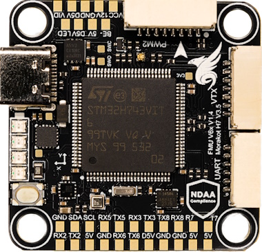

Morakot Flight Controller — NDAA-Compliant. Made in Taiwan. Built for Performance. Engineered, tested, and manufactured in Taiwan, the Morakot Flight Controller meets full NDAA compliance, ensuring trusted quality and security for professional applications. With an integrated Ethernet interface, it delivers high-speed, reliable connectivity for next-generation FPV and unmanned aerial systems.
Pinout


Features
Sensors
Microprocessor
STM32H743VIT MCU * 480Mhz / 1MB RAM / 2MB Flash
Power
3S–8S DC Input power
5V 2A BEC peripherals power
12V 2A BEC video power
Other
LED Indicators
Battery voltage indicator LED
MicroSD Slot
9x motor outputs
8x UART
1x I2C
1x CAN
1x Ethernet
UART Mapping
UART Mapping The UARTs are marked Rn and Tn in the above pinouts. The Rn pin is the receive pin for UARTn. The Tn pin is the transmit pin for UARTn.
Port |
UART |
Protocol |
TX DMA |
RX DMA |
|---|---|---|---|---|
0 |
USB |
MAVLink2 |
✘ |
✘ |
1 |
USART1 |
MSP_DisplayPort |
✔ |
✔ |
2 |
USART2 |
MAVLink2 |
✔ |
✔ |
3 |
USART3 |
None |
✔ |
✔ |
4 |
UART5 |
GPS |
✔ |
✔ |
5 |
USART6 |
ESCTelemetry |
✔ |
✔ |
6 |
UART7 |
MAVLink2 |
✔ |
✔ |
7 |
UART8 |
RCIN |
✔ |
✔ |
-RTS/CTS flow control is available on UART7.
VTX Support
The JST-GH 7p connector supports a DJI Air Unit / HD VTX connection. Protocol defaults to DisplayPort. Pin 1 of the connector is 12v so be careful not to connect this to a peripheral that can not tolerate this voltage.
Physical Information
Dimensions: 38.5 x 30.5 mm
Height: up to 8.5 mm
Mounting: 30.5 x 30.5 mm (M3/M4 with dampers)
Weight: 7 g
More Information
Connectors
ESC1 - 8 Pin JST-GH
Pin |
Signal Name |
Voltage |
|---|---|---|
1 |
VBAT IN |
12V-33.6V |
2 |
UART6_RX |
3.3V |
3 |
GND |
3.3V |
4 |
CURRENT |
3.3V |
5 |
MOTOR/SERVO 1 |
3.3V |
6 |
MOTOR/SERVO 2 |
3.3V |
7 |
MOTOR/SERVO 3 |
3.3V |
8 |
MOTOR/SERVO 4 |
3.3V |
ESC2 - 8 Pin JST-GH
Pin |
Signal Name |
Voltage |
|---|---|---|
1 |
VBAT IN |
12V-33.6V |
2 |
MOTOR/SERVO 9 |
3.3V |
3 |
GND |
3.3V |
4 |
CURRENT |
3.3V |
5 |
MOTOR/SERVO 5 |
3.3V |
6 |
MOTOR/SERVO 6 |
3.3V |
7 |
MOTOR/SERVO 7 |
3.3V |
8 |
MOTOR/SERVO 8 |
3.3V |
CAN - 4 Pin JST-GH
Pin |
Signal Name |
Voltage |
|---|---|---|
1 |
5.0V |
5.0V |
2 |
CAN1_H |
5.0V |
3 |
CAN1_L |
5.0V |
4 |
GND |
GND |
GPS - 6 Pin JST-GH
Pin |
Signal Name |
Voltage |
|---|---|---|
1 |
5.0V |
5.0V |
2 |
UART5_TX |
3.3V |
3 |
UART5_RX |
3.3V |
4 |
I2C1_SCL |
3.3V |
5 |
I2C1_SDA |
3.3V |
6 |
GND |
GND |
UART(TELEM) - 6 Pin JST-GH
Pin |
Signal Name |
Voltage |
|---|---|---|
1 |
5.0V |
5.0V |
2 |
UART7_TX |
3.3V |
3 |
UART7_RX |
3.3V |
4 |
UART7_CTS |
3.3V |
5 |
UART7_RTS |
3.3V |
6 |
GND |
GND |
VTX - 7 Pin JST-GH
Note: connector pinout not in same order as standard HD VTX cabling
Pin |
Signal Name |
Voltage |
|---|---|---|
1 |
VIDEO |
na |
2 |
12.0V |
12.0V |
3 |
GND |
GND |
4 |
USART1_RX |
3.3V |
5 |
USART1_TX |
3.3V |
6 |
GND |
3.3V |
7 |
USART3_RX |
GND |
SPI (external OSD or IMU) - 6 Pin JST-SH
Pin |
Signal Name |
Voltage |
|---|---|---|
1 |
5.0V |
5.0V |
2 |
SPI4_MOSI |
3.3V |
3 |
SPI4_MISO |
3.3V |
4 |
SPI4_SCK |
3.3V |
5 |
SPI4_CS |
3.3V |
6 |
GND |
GND |
RC - 4 Pin JST-GH
Pin |
Signal Name |
Voltage |
|---|---|---|
1 |
5.0V |
5.0V |
2 |
UART8_RX |
3.3V |
3 |
UART8_TX |
3.3V |
4 |
GND |
GND |
ETH - 4 Pin JST-GH
Pin |
Signal Name |
Voltage |
|---|---|---|
1 |
RXN |
3.3V |
2 |
RXP |
3.3V |
3 |
TXN |
3.3V |
4 |
TXP |
3.3V |
RC Input
RC input is via SERIAL7(UART8) on the RC connector. Unidirectional protocols can be connected to R8. Bi-Directional Protocols will use the T8 pin also.
PPM is not supported.
SBUS/DSM/SRXL connects to the RX8 pin.
FPort requires connection to TX8. Set SERIAL7_OPTIONS = 7
CRSF/ELRS also requires both TX8 and RX8 connections and provides telemetry automatically. In order to use the SBUS pin on the HD VTX connector, you must change SERIAL7_PROTOCOL to something other than “23” and set SERIAL3_PROTOCOL:raw-html-m2r:` to “23”.
PWM Outputs
The Morakot supports up to 9 PWM outputs. All are DSHot and Bi-Directional DShot capable
The PWM is in 3 groups:
PWM 1-4 in group1
PWM 4-8 in group2
PWM 9 (LED) in group3
Channels within the same group need to use the same output rate. If any channel in a group uses DShot then all channels in that group need to use DShot.
Compass
The Morakot has a built-in compass. Due to potential interference, the autopilot is usually used with an external I2C compass as part of a GPS/Compass combination and the internal compass disabled.
OSD
DisplayPort OSD is enabled by default on the HD VTX connector.
Firmware
Firmware for this board can be found here in sub-folders labeled “Morakot”
Loading Firmware
Initial firmware load can be done with DFU by plugging in USB with the bootloader button pressed. Then you should load the “XXX_bl.bin” firmware, using your favorite DFU loading tool. Once the initial firmware is loaded you can update the firmware using any ArduPilot ground station software. Updates should be done with the “*.apj” firmware files.