Radio Control Systems

This article provides an overview of the RC Transmitter and Receiver Systems that can be used with ArduPilot autopilots.
Compatible RC Protocols
ArduPilot autopilots are compatible with the following receiver output protocols:
PPM-Sum receivers
SBus receivers
Fast SBus (from DJI HDL video/RC systems)
i-BUS receivers
CRSF receivers (including ExpressLRS systems)
mLRS (with telemetry) (MAVLink)
DroneCAN peripherals can decode these RC protocols on a peripheral and pass to the autopilot
MAVLink connected RC (not to be confused with MAVLink RC Overrides used for CS joystick control of RC functions)
Parallel PWM outputs encoded to PPM-Sum using an external encoder (see below, not supported on many autopilots now)
Connecting the Receiver
For all protocols above, ArduPilot auto-detects the protocol of the RC receiver system. However, depending on the protocol and autopilot type, the physical connection to the autopilot may differ.
Some protocols, most notably SRXL2, CRSF, and ELRS, require a full UART connection.
In addition other protocols that also provide telemetry, like FPort, would generally require a bi-directional half-duplex connection in order to obtain telemetry. For these protocols the TX output of the UART should be connected to the serial input of the receiver. It is also possible on F7 and H7 boards to connect to the UART RX input with some additional configuration.
PPM-Sum/SBus/i-BUS
These receivers are usually connected to the RCin or SBUS input pin on the autopilot.
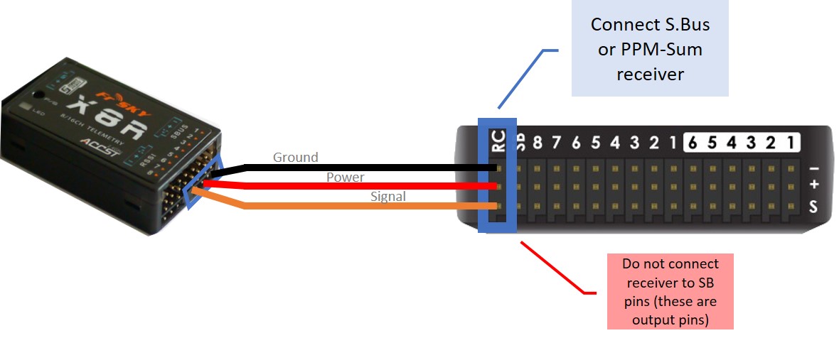
To connect a PPM-Sum receiver or an SBus receiver to a Pixhawk, for example, plug the ground (black), power (red) and signal (usually white - orange in the diagram below) wires to the RC pins on the Pixhawk.

Tip
The parameter to enable the SBus output from the PixHawk style autopilots is BRD_SBUS_OUT. This is only to pass SBus externally to other devices, like servos. Not to connect a receiver to RCin or SBus In.
DSM/DSM2/DSM-X/SRXL/SUM-D
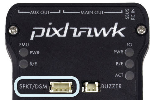
For autopilots that do not provide a separate DSM input, these can be connected as above. However, for performance reasons on autopilots that use an IOMCU (The Pixhawk/Cube family), the autopilot’s DSM input connection is highly recommended.

FPort/FPort2
FPort is a bi-directional protocol, using SBus RC in one direction, and serial telemetry in the other. The RC portion can be decoded when attached to an autopilot as if it were SBus, but the embedded telemetry would be lost. See the FPort setup documentation for details on connection to one of the autopilots Serial Ports.
mLRS
mLRS can provide RC control and MAVLink telemetry. mLRS receivers have an RC output pin that can be configured for either SBUS or CRSF protocol (CRSF would be only RC data). For SBUS you can connect it to the autopilot’s RCin pin. For CRSF or SBUS, it can be connected to any autopilot UART RX pin and that port configured for RC protocol. Using CRSF portocol, allows RSSI/LQ information to be delivered to the autopilot.
For optional telemetry a separate TX/RX port is provided on the receiver to be connected to an autopilot MAVLink telemetry serial port. You can omit the single wire RC connection and configure the mLRS receiver to output RC channels over MAVLink if you are not using GCS RC overrides (eg, joystick)
SRXL2/CRSF/ELRS
These bi-directional protocols require the use of a Serial Port. See links below for setup and connections.
IRC Ghost
This requires a connection to a full UART port via its TX pin. The port should be set for half-duplex RC input:
using SERIAL2 as the port:
SERIAL2_PROTOCOL = 23 (RCinput)
SERIAL2_OPTIONS = 4 (Half-Duplex)
RSSI_TYPE = 3
RC input to Serial Port
Note
any UART RX input will auto-detect all the protocols (except PPM, or SRXL2/CRSF/ELRS which also require connection of the UART’s TX pin), if the serial port protocol is set to 23 (for example, generally, SERIAL2_PROTOCOL for the TELEM2 UART if used). The exception to this is for SBUS attached to UARTs on F4 based autopilots. This requires an external inverter since SBUS is inverted and F4 autopilots do not have selectable inversion on their UART pins.
Note
The serial port baudrate is automatically set and controlled by the firmware when any serial RC protocol is detected.
Radio System Selection
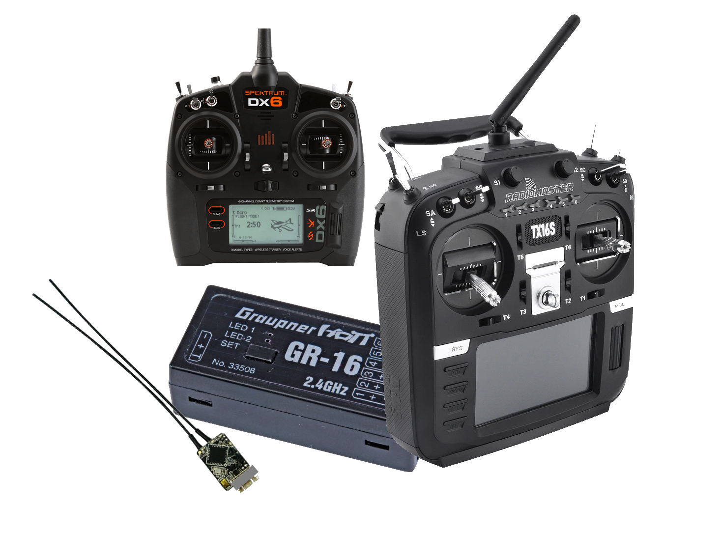
Selection will depend on many factors: range,telemetry requirements, cost, compatibility with existing equipment, etc. Most manufacturers often many different models with differing capabilities. Many systems have been reverse-engineered and “cloned” by other manufacturers offering more economical versions of transmitters and receivers. Many Transmitters offer multiple protocols and are based on the OpenTX firmware which is extremely flexible and also allows the use of LUA scripts to display telemetry data on their LCD screens.
Range
RC control range varies greatly depending on system used, installation, antennas used, terrain, and even weather conditions. But in general, for discussion purposes here, RC systems can be categorized into Short Range (2km and under) , Medium (2-10km) and Long Range (>10km). In addition, they may offer uni-directional (Vehicle to Transmitter) or bi-directional (Vehicle to/from Transmitter) telemetry.
Telemetry
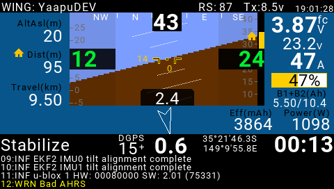
FrSky Horus Transmitter running Yaapu LUA script

Some systems provide transparent radio modems sending the telemetry from the autopilot, and others have proprietary protocols. Those with proprietary protocols often have means of displaying telemetry data on the transmitter display itself, like FRSky or OpenTX based Transmitters.
Telemetry speeds vary from 56K to 1-2K baud depending on protocol and, in some cases, distance. Often telemetry range will be less than radio control range.
Consult
Number of channels
ArduPilot requires at least 5 channels for most vehicles, however, 8 to 16 channels are commonly available in most systems and are very convenient for controlling other vehicle functions such as cameras or flight feature options. Many vehicles require 8 channels just for basic operation, such as many QuadPlanes.
Below is a table with some commonly available systems showing these elements. Note, not all versions of transmitters and/or receivers from a particular manufacturer may have these characteristics. Note: that many “clone” or “compatible” versions of this systems also exist, only the OEM system is listed.
Original Manufacturer |
Range |
Telemetry |
Telem Speed |
TX Display |
RC Protocol |
Notes |
|---|---|---|---|---|---|---|
Flysky |
Short |
Yes |
yes |
i-BUS/SBUS |
7 |
|
FrSky X series |
Short |
Bi-dir |
Medium |
yes |
PPM-SUM/SBUS/ FPort |
2 |
Futaba |
Short |
No |
SBus |
|||
Graupner |
Short |
Yes |
Medium |
yes |
SUM-D |
|
Multiplex |
Short |
No |
SRXL |
|||
Spektrum |
Short |
Vendor Specific |
yes |
DSM/DSM2 DSM-X/ SRXL |
||
FrSky R9 series |
Medium |
Bi-dir |
Medium |
yes |
PPM-SUM/SBUS/ FPort |
2 |
IRC Ghost |
Medium |
Vendor Specific |
yes |
IRC Ghost |
||
CRSF |
Long |
Bi-dir |
Variable |
yes |
SBUS/CRSF |
3 |
DragonLink |
Long |
Bi-dir |
56K |
via MTP/LUA |
PPM_SUM/SBUS |
1 |
ELRS |
Long |
Bi-Dir |
Variable |
optional |
|
4 |
HereLink |
Long |
Bi-dir |
56K |
integrated |
SBUS |
8 |
mLRS |
Long |
Bi-dir |
12K - 91K |
via LUA |
SBUS/CRSF |
5 |
SIYI |
Long |
Bi-dir |
56K |
integrated |
SBUS |
8 |
Note 1: DragonLink provides a 56Kbaud transparent link for telemetry, allowing full MAVLink telemetry to/from the vehicle from the transmitter module. Dragonlink is an add-on module to the transmitter, such as an FRSky Taranis or RadioMaster T16. See DragonLink RC Systems. MTP (Mavlink to Passthru) converters are available to allow direct display of MAVLink Telemetry data on OpenTX transmitters using Yaapu Telemetry LUA Script.
Note 2: See Yaapu FrSky Telemetry Script for OpenTX. The ability to change parameters over FRSky telemetry from an Open TX compatible transmitter in addition to displaying the telemetry data is possible. Most FRSky compatible transmitters use OpenTX. Note that R9 systems are not quite Long Range, but much further range than normal FRSky systems, themselves at the very high end of the Short Range category at 1.6-2km range.
Note 3: ArduPilot provides a means to send its telemetry data via CRSF such that it can be displayed on OpenTX transmitters using the Yaapu Telemetry LUA Script. The ability to change parameters over CRSF telemetry from an Open TX compatible transmitter in addition to displaying the telemetry data is also possible. See TBS Crossfire Telemetry
Note 4: ELRS (ExpressLRS) is a flexible open-source system that can output CRSF, SBUS, or MAVLink (with embedded RC) protocols. Telemetry requires the use of CRSF or Mavlink, and the receiver must be wired to a full UART. See ExpressLRS site <https://www.expresslrs.org/> and TBS CRSF/ ELRS for more information.
Note 5: The mLRS project is firmware designed specifically to carry both RC and MAVLink. The usable telemetry speed varies by the chosen mode and is managed via RADIO_STATUS flow control. It uses the CRSF (TBS Crossfire) RC protocol on both the receiver and Tx module. It also integrates full MAVLink telemetry via serial connections on the Tx module and the receiver.
Note 6: Vendor Specific Telem means that they accomodate sensor additions to the vehicle and can display the information on certain Vendor specific TXs but do not send ArduPilot telemetry from the vehicle to ArduPilot compatible GCS or OpenTX display scripts.
Note 7: The receiver must support i-BUS telemetry (look for a SENS port on the receiver or check the product specifications).
Note 8: These systems have integrated HD video transmission from Ethernet or HDMI camera systems in addition to RC control and vehicle telemetry.
Links to Radio Control Systems
Without integrated telemetry:
With integrated telemetry:
Multi-Protocol:
Recommendations:
Its difficult to make a recommendations since there is such a wide spectrum of capabilities, features, and costs.
In Europe, Multiplex and Graupner are well established systems and comply with EU radiation recommendations (as do many other brands as an option).
Flysky produces very low cost, low end systems.
FRSky and Spektrum enjoy the largest established bases with Spektrum dominant in park flyer and entry level RC systems. FRSky has telemetry capabilities and utilizes OpenTX which is very flexible and is continually adding features in the firmware.
The Jumper T16 and RadioMaster T16 are FRSky Horus-like OpenTX based transmitter clones with multiple RC protocols built-in.
PPM encoders
A PPM Encoder will allow you to use any older style RC receiver that has only PWM outputs for each channel instead of an SBUS or PPM output. See PPM encoders for more information. This protocol is not being included on many new autopilots and is being slowly obsoleted.