AtomRC F405-NAVI-Deluxe
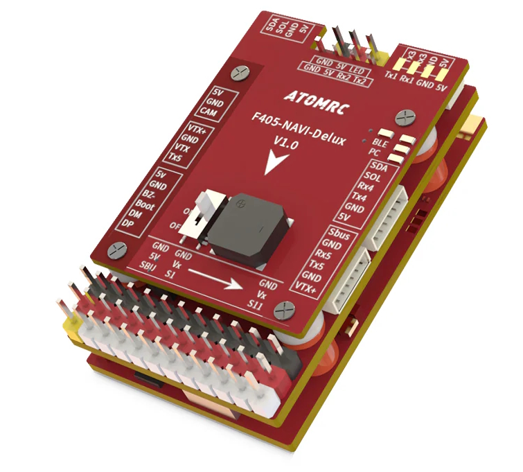
the above image and some content courtesy of ATOMRC
Note
- Due to flash memory limitations, this board does not include all ArduPilot features.
See Firmware Limitations for details.
Specifications
Processor
STM32F405RGT6 ARM (168MHz)
AT7456E OSD
ESP32 Bluetooth RF module
Sensors
ICM-42688 IMU (accel, gyro)
SPL-06 barometer
Voltage & 120A current sensor
Power
6V ~ 30V DC input power
5V, 5A BEC for servos
5V or 9V, 2A BEC for video
Interfaces
6x UARTS
12x PWM outputs (PWM12 defaults to serial LED)
SBUS input; compatible with all ArduPilot supported RC systems except PPM
I2C port for external compass and airspeed sensor
Type-C USB port
SD Card Slot
6 pin JST-GH for GPS/Compass
6 pin JST-GH for HD Video air units
6 pin JST-GH for remote USB/Buzzer included with autopilot
Size and Dimensions
50mm x 30mm x 12mm
21g
Where to Buy
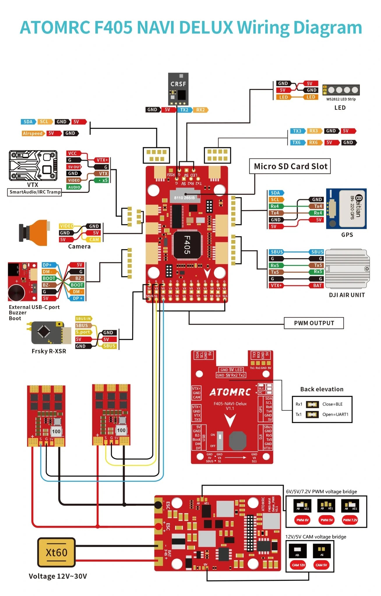
Pinout
Default UART order
Name |
UART |
Default Protocol |
|---|---|---|
SERIAL0 |
USB |
MAVLink2 |
SERIAL1 |
USART1 |
MAVLink2 (internal BLE RF Module currently not supported by ArduPilot GCS) |
SERIAL2 |
SART2 |
RCinput, DMA capable (RX2 connected to SBUS pins via inverter) |
SERIAL3 |
USART3 |
USER |
SERIAL4 |
UART4 |
GPS1 |
SERIAL5 |
UART5 |
DisplayPort |
SERIAL6 |
USART6 |
USER, DMA capable |
Serial protocols shown are defaults, but can be adjusted to personal preferences.
Dshot capability
All motor/servo outputs are Dshot and PWM capable. Outputs 1/2, and 5/6 are Bi-Directional DSHOT capable. However, mixing Dshot and normal PWM operation for outputs is restricted into groups, ie. enabling Dshot for an output in a group requires that ALL outputs in that group be configured and used as Dshot, rather than PWM outputs.
The output groups are:
1/2
3/4
5/6/7
8/9/10
11/12(LED).
Note
output 12 is marked as “LED” and defaulted for serial led protocol. If output 11 is to be used, then SERVO12_FUNCTION must be changed to “0” or some other normal servo/motor function.
RC Input
USART2 is defaulted for RC input. The SBUS pins are passed through an inverter to RX2 (UART2 RX). SBUS/FPort should be connected to an SBUS input, However, FPort, when connected in this manner, can provide RC but without telemetry.
Other RC protocols:
PPM is not supported.
DSM/SRXL connects to the RX6 pin
FPort requires connection to TX2 and RX2 via a bi-directional inverter. See FPort Receivers.
CRSF/ELRS also requires a TX2 connection, in addition to RX2, and automatically provides telemetry.
SRXL2 requires a connection to TX2 and automatically provides telemetry. Set SERIAL2_OPTIONS to “4”.
Note
the 5v pin above the SBUS pin is powered when USB is connected. All other 5V pins are only powered when battery is present.
RF Module
A BLERF module is integrated on board and connected to USART1, but is not currently supported by ArduPilot Ground Control stations. This module is powered off by default, but power to it can be controlled by setting up a relay function:
Enable a relay via RELAYx_EN and set its RELAYx_PIN to “81” to control the switching. Then select an RC channel for control (Chx) and set its RCx_OPTION to the appropriate Relay (1-6) that you had set its pin parameter above. RELAY 2 is assigned by default to this GPIO pin, but would need RELAY2_FUNCTION set to “1” to enable it.
Battery Monitor Configuration
These settings are set as defaults when the firmware is loaded (except BATT_AMP_PERVLT which needs to be changed from the default value). However, if they are ever lost, you can manually set the parameters:
Enable Battery monitor.
BATT_MONITOR =4
Then reboot.
BATT_AMP_PERVLT 78.4
Connecting a GPS/Compass module
This board does not include a GPS or compass so an external GPS/compass should be connected as shown below in order for autonomous modes to function.
Firmware
Firmware for this board can be found here in sub-folders labeled “ATOMRCF405NAVI-Deluxe”.
Initial firmware load can be done with DFU by plugging in USB with the bootloader button pressed. Then you should load the “with_bl.hex” firmware, using your favourite DFU loading tool.
Once the initial firmware is loaded you can update the firmware using any ArduPilot ground station software. Updates should be done with the *.apj firmware files.