ACNS-CM4Pilot
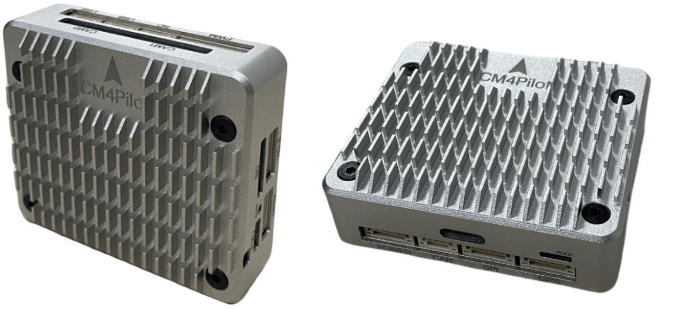
The ACNS-CM4Pilot is a low-cost and compact flight controller which integrates a Raspberry Pi CM4 onboard as its Companion computer.
Specifications
Processor
STM32F405 ARM (168MHz)
Broadcom BCM2711, quad-core Cortex-A72 (ARM v8) 64-bit SoC @ 1.5GHz (Raspberry Pi CM4)
Sensors
BMI088 IMU (accel, gyro)
BMP280 barometer
LIS3MDLTR magnetometer
Interfaces (Autopilot)
8x PWM outputs DShot capable
1 CAN
1x RC input
5x UARTs/serial for GPS and other peripherals, one normally used for RC input, one for CM4 connection
I2C port for external compass, airspeed, etc.
Power module input
microSDCard for logging, etc.
USB-C port
Analog RSSI/Airspeed input
DFU boot button
Interfaces (CM4)
4 USB, 1 OTG USB-C ports
microSDCard
2x GPIO
UART
2x Camera Interfaces
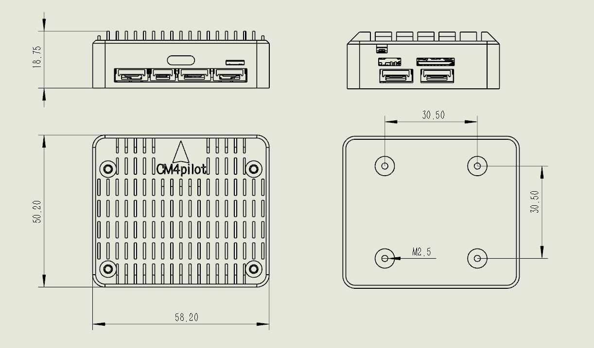
Size and Dimensions
Where to Buy
???
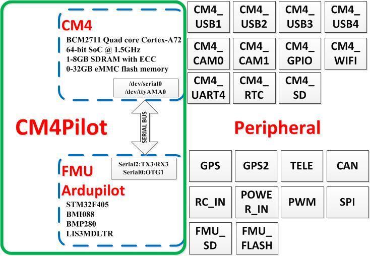
Block Diagram
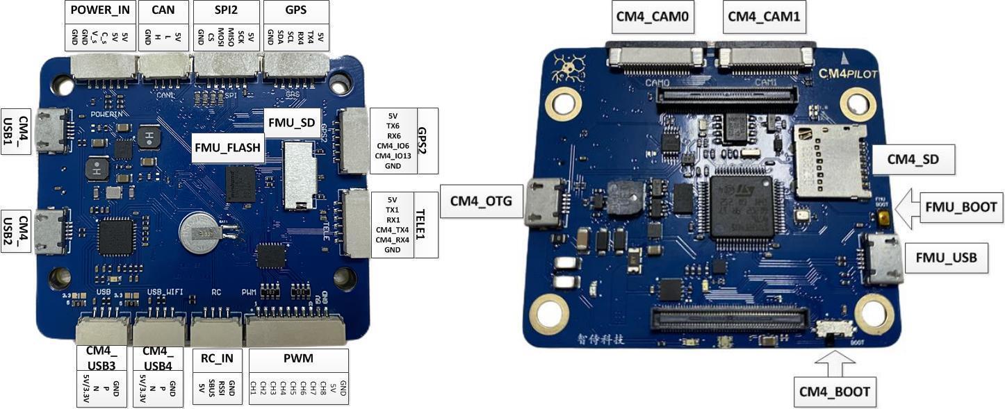
Pinouts
Default UART order
The UARTs are marked RXn and TXn in the above pinouts. The RXn pin is the receive pin for UARTn. The TXn pin is the transmit pin for UARTn.
SERIAL0 -> USB(OTG1)
SERIAL1 -> USART1(Telem1)(DMA capable)
SERIAL2 -> USART3 (CM4)(DMA capable)
SERIAL3 -> UART4 (GPS)(DMA capable)
SERIAL4 -> UART6 (GPS2)(DMA capable)
SERIAL5 -> USART2 (SBUS)(RC input, not DMA capable)(RX2 can be re-configured as a normal UART input using BRD_ALT_CONFIG = 1
Serial protocols shown are defaults, but can be adjusted to personal preferences.
Servo/Motor Outputs
All motor/servo outputs are Dshot and PWM capable. However, mixing Dshot, serial LED, and normal PWM operation for outputs is restricted into groups, ie. enabling Dshot for an output in a group requires that ALL outputs in that group be configured and used as Dshot, rather than PWM outputs.
PWM 1-2 in group1
PWM 5,6 in group2
PWM 7,8 in group3
PWM 8-10 in group4
RC Input
The SBUS pin can be used for all ArduPilot supported receiver protocols, except CRSF/ELRS and SRXL2 which require a true UART connection. However, FPort, when connected in this manner, can provide RC without telemetry.
To allow CRSF and embedded telemetry available in Fport, CRSF, and SRXL2 receivers a UART must be configured and used (USART1 , UART4, or UART6) and their SERAILx_PROTOCOL set to “23”.
With this option:
PPM is not supported. SBUS requires an inverter.
FPort requires connection to TX2 and RX2 via a bi-directional inverter. See FPort Receivers.
SRXL2 requires SERIAL2_OPTIONS to “4”.
Battery Monitor Configuration
These settings are set as defaults when the firmware is loaded for a typical external analog power monitor. You will need to adjust BATT_VOLT_MULT and BATT_AMP_PERVLT 17 for whichever monitor is used.
Enable Battery monitor.
BATT_MONITOR =4
Then reboot.
BATT_VOLT_MULT 10.1
Buzzer
An internal buzzer to play ArduPilot musical notification tones is provided on board.
Warning
sometimes it is possible that integrated tone alarms will inject noise into the on board IMUs. Users may want to set NTF_BUZZ_TYPES to disable the built in buzzer to assure this does not occur inflight.
Firmware
This board does not come with ArduPilot firmware pre-installed. Use instructions here to load ArduPilot the first time Loading Firmware onto boards without existing ArduPilot firmware.
Firmware for this board can be found here in sub-folders labeled “ACNS-CM4Pilot”.