PixSurveyA2-IND
The PixSurveyA2-IND flight controller is sold by a range of resellers listed on the makeflyeasy(http://www.makeflyeasy.com)
Features
STM32H743VIT6 microcontroller
STM32F103C8T6 IOMCU microcontroller
- 3x IMUs, 2- ICM-42652(SPI), one ICM42688-P(SPI)
internal heater for IMUs temperature control
internal Soft Rubber Damping Ball isolation for All interna IMUs
2x barometers, BMP388(SPI)
Built-in RAMTRON(SPI)
microSD card slot
5 UARTs
USB(Type-C)
PPM & S.Bus input
14 PWM outputs
Two I2C ports and Two FDCAN ports, with multiple connectors
S.Bus output
internal Buzzer
Two power module inputs, one analog and one CAN
Independent power input for servo rail BEC
External safety Switch
Where to Buy
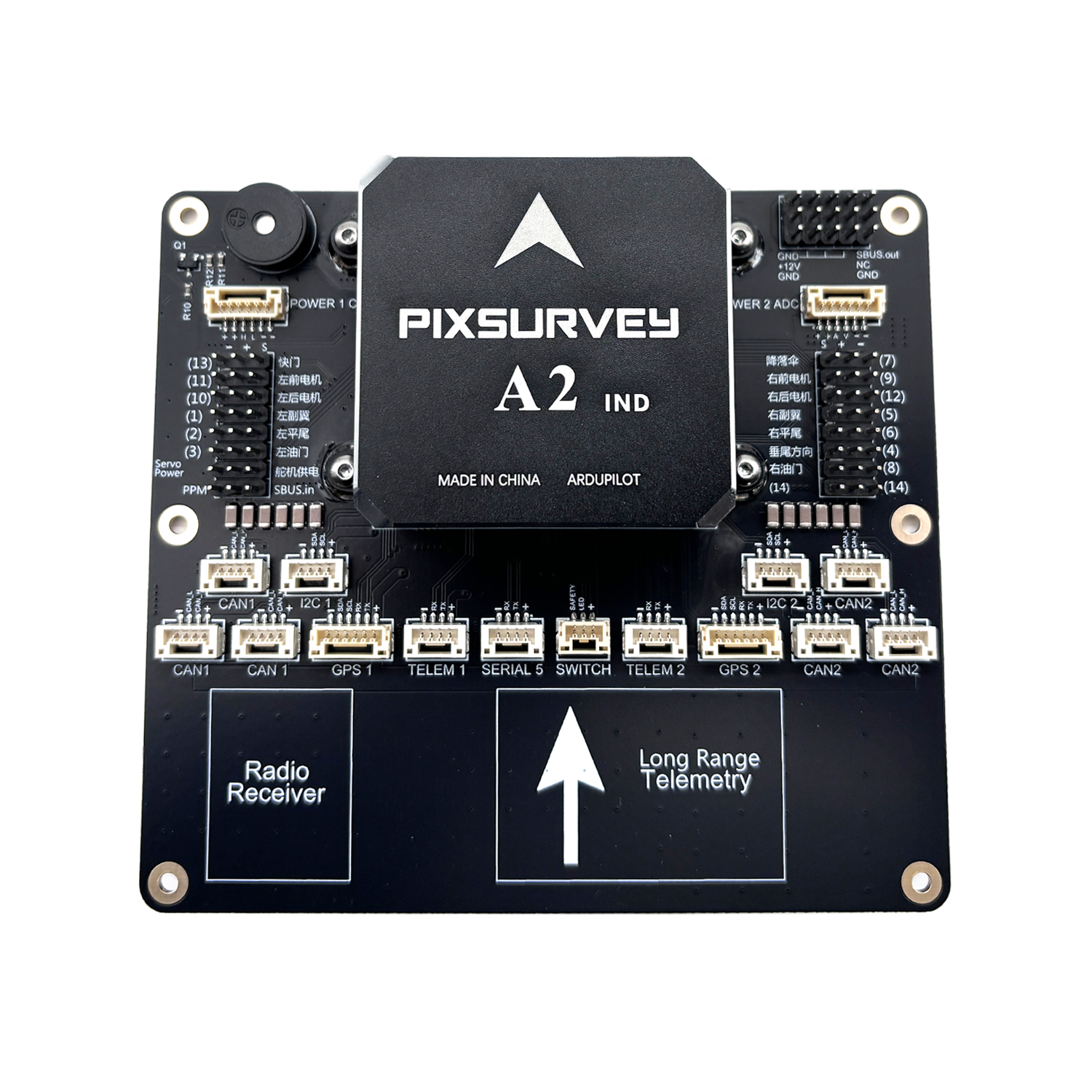
Pinout
UART Mapping
SERIAL0 -> console MAVLink2, USB)
SERIAL1 -> USART2 (Telem1, MAVLINK2) (DMA capable)
SERIAL2 -> USART3 (Telem2, MAVLink2) (DMA capable)
SERIAL3 -> UART4 (GPS1) (TX is DMA capable)
SERIAL4 -> UART8 (GPS2) (RX is DMA capable)
SERIAL5 -> UART7 (USER)
Connectors
POWER_CAN1 port
| PIN | SIGNAL | VOLT |
|---|---|---|
| 1 | VCC | +5V |
| 2 | VCC | +5V |
| 3 | CAN_H | +12V |
| 4 | CAN_L | +12V |
| 5 | GND | GND |
| 6 | GND | GND |
TELEM1, TELEM2 ports
| Pin | Signal | Volt |
|---|---|---|
| 1 | VCC | +5V |
| 2 | TX (OUT) | +3.3V |
| 3 | RX (IN) | +3.3V |
| 4 | GND | GND |
I2C1, I2C2 ports
| PIN | SIGNAL | VOLT |
|---|---|---|
| 1 | VCC | +5V |
| 2 | SCL | +3.3V |
| 3 | SDA | +3.3V |
| 4 | GND | GND |
CAN1, CAN2 ports
| PIN | SIGNAL | VOLT |
|---|---|---|
| 1 | VCC | +5V |
| 2 | CAN_H | +12V |
| 3 | CAN_L | +12V |
| 4 | GND | GND |
Safety and buzzer port(labeled SWITCH)
| PIN | SIGNAL | VOLT |
|---|---|---|
| 1 | VCC | +5V |
| 2 | LED | +5V |
| 3 | Safety Switch | +5V |
GPS1/I2C1, GPS2/I2C2 ports
| PIN | SIGNAL | VOLT |
|---|---|---|
| 1 | VCC | +5V |
| 2 | TX | +3.3V |
| 3 | RX | +3.3V |
| 4 | SCL | +3.3V |
| 5 | SDA | +3.3V |
| 6 | GND | GND |
Serial5 port
| Pin | Signal | Volt |
|---|---|---|
| 1 | VCC | +5V |
| 2 | TX (OUT) | +3.3V |
| 3 | RX (IN) | +3.3V |
| 4 | GND | GND |
Power2 ADC ports
| PIN | SIGNAL | VOLT |
|---|---|---|
| 1 | VCC | +5V |
| 2 | VCC | +5V |
| 3 | CURRENT | +3.3V |
| 4 | VOLTAGE | +3.3V |
| 5 | GND | GND |
| 6 | GND | GND |
RC Input
All compatible unidirectional RC protocols can be decoded by attaching the Receiver’s output to the SBUS input pin next to the Servo/Output VCC input connector.
To allow CRSF and embedded telemetry available in Fport, CRSF, and SRXL2 receivers, a full UART with DMA, such as SERIAL2 would need to be used for receiver connections. Below are setups using Serial6.
SERIAL2_PROTOCOL should be set to “23”.
FPort would require SERIAL2_OPTIONS be set to “15”.
CRSF/ELRS would require SERIAL2_OPTIONS be set to “0”.
SRXL2 would require SERIAL2_OPTIONS be set to “4” and connects only the TX pin.
PWM Outputs
The autopilot supports up to 14 PWM outputs. All 14 outputs support all normal PWM output formats. All outputs also support DShot. Outputs 9-14 support Bi-Directional DShot. Outputs within the same timer group need to use the same output rate. If any output in a group uses DShot then all channels in the group need to use DShot,etc..
Outputs 1 and 2 in group1
Outputs 3 and 4 in group2
Outputs 5, 6, 7 and 8 in group3
Outputs 9-12 in group4
Outputs 13 and 14 in group5
GPIOs
All PWM outputs can be used as GPIOs (relays, camera, RPM etc). To use them you need to set the output’s SERVOx_FUNCTION to -1. The numbering of the GPIOs for PIN variables in ArduPilot is:
| IO Pins | FMU Pins | |||||
|---|---|---|---|---|---|---|
| Name | Value | Option | Name | Value | Option | |
| M1 | 101 | Out1 | M9 | 50 | AuxOut1 | |
| M2 | 102 | Out2 | M10 | 51 | AuxOut2 | |
| M3 | 103 | Out3 | M11 | 52 | AuxOut3 | |
| M4 | 104 | Out4 | M12 | 53 | AuxOut4 | |
| M5 | 105 | Out5 | M13 | 54 | AuxOut5 | |
| M6 | 106 | Out6 | M14 | 55 | AuxOut6 | |
| M7 | 107 | Out7 | ||||
| M8 | 108 | Out8 | ||||
Battery Monitor Settings
These should already be set by default. However, if lost or changed:
Enable Battery monitor with these parameter settings : * BATT1_MONITOR 8 (DroneCAN) * BATT2_MONITOR 4 (Analog)
Then reboot. * BATT2_VOLT_PIN 13 * BATT2_CURR_PIN 4 * BATT2_VOLT_MULT 18.0 * BATT2_AMP_PERVLT 24.0
Note
OSDs will by default display the first battery monitor unless the second battery monitor panel is setup in OSD parameters.
DroneCAN
There are 6 CAN ports which allow connecting two independent CAN bus outputs. Each of these can have multiple CAN peripheral devices connected. There are also two separate CAN POWER ports for easy access to CAN-PMU.
Loading Firmware
The board comes pre-installed with an ArduPilot compatible bootloader, allowing the loading of xxxxxx.apj firmware files with any ArduPilot compatible ground station.
Firmware for these boards can be found here in sub-folders labeled “PixSurveyA2-IND”.