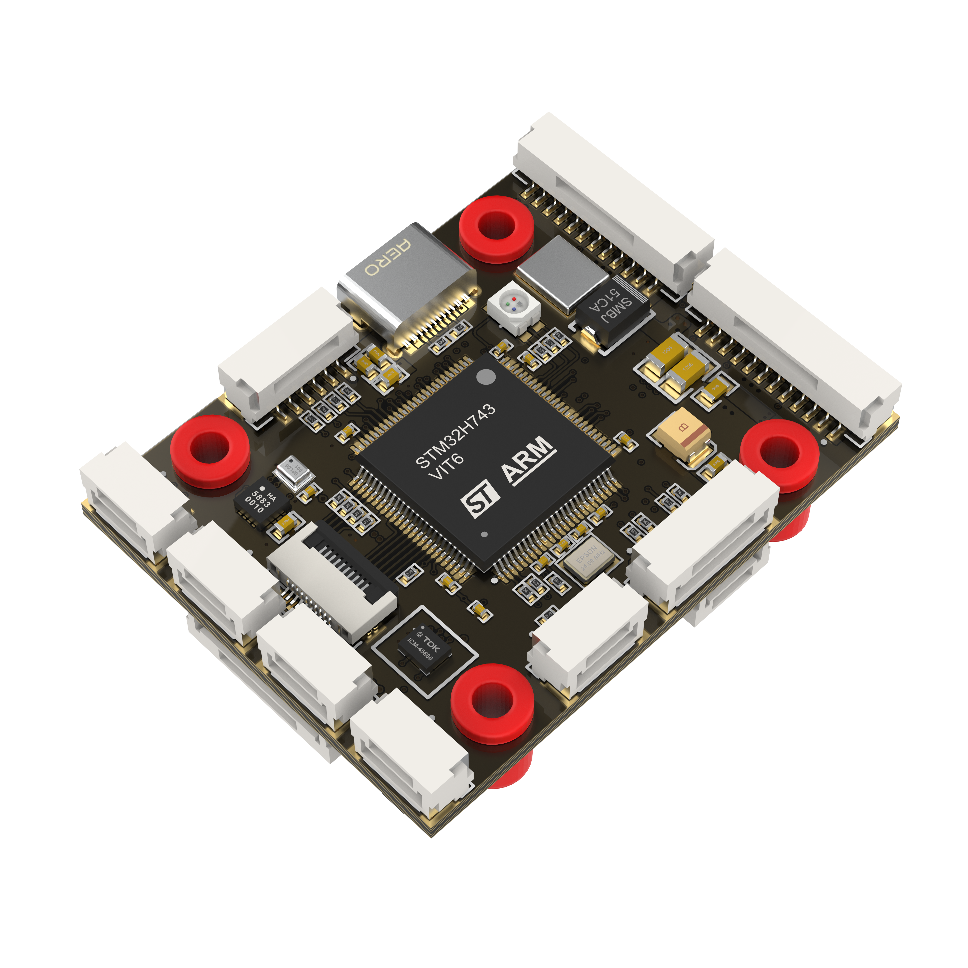
AEROFOX-H7 Flight Controller
The AEROFOX-H7 is a flight controller produced by AEROFOX
Features
Processor
    STM32H743

Sensors
    ADIS16470 (appears in the advanced version)
    ICM45686 (appears in the advanced version)
    ICM42688
    QMC5883L
    SPL06-001

Power
    2S-12S (MAX60V) Lipo input voltage
    5V BEC for system power supply( 5V peripheral current limit 1.2A)
    5V/12V BEC for VTX( Current limit 2.5A, need strong heat dissipation)
    Dual power automatic switching and condition monitoring

Interfaces
    16x PWM output
    7x UARTs for RC, TELEM, GPS and other peripherals
    2x I2C ports for external compass, airspeed, baro
    2x CAN port
    4x Relay output
    4x ADC input

FPC connector
    The connector includes an SPI, an I2C, an PWM IMU heating control pin.
Pinout

UART Mapping
All UARTs, except UART1, are DMA enabled. UART corresponding to each SERIAL port, and its default protocol, are shown below:
SERIAL0 -> USB (MAVLink2)
SERIAL1 -> UART7 (ESC Telemetry)
SERIAL2 -> UART4 (User configured)
SERIAL3 -> UART5 (User configured)
SERIAL4 -> USART2 (User configured)
SERIAL5 -> USART1 (GPS)
SERIAL6 -> UART8 (RCIN)
SERIAL7 -> USART3 (MAVLink2)
Any UART may be re-tasked by changing its protocol parameter.
RC Input
RC input is configured on the RX6 (UART6_RX) pin. It supports all RC protocols except PPM. See Radio Control Systems for details for a specific RC system. SERIAL6_PROTOCOL is set to “23”, by default, to enable this.
SBUS/DSM/SRXL connects to the RX6 pin.
FPort requires connection to TX6 and SERIAL6_OPTIONS be set to “7”.
CRSF also requires a TX6 connection, in addition to R6, and automatically provides telemetry. Set SERIAL6_OPTIONS
SRXL2 requires a connection to TX6 and automatically provides telemetry. Set SERIAL6_OPTIONS to “4”.
PWM Output
The AEROFOXH7 support up to 16PWM outputs. All pins also support DShot. Outputs 1-8 support Bi-Directional DShot.
The 16 PWM outputs are in 9 groups:
PWM 1,2 in group1
PWM 3,4 in group2
PWM 5,6 in group3
PWM 7,8 in group4
PWM 9,10 in group5
PWM 11 in group6
PWM 12 in group7
PWM 13,14 in group8
PWM 15,16 in group9
Channels within the same group need to use the same output rate. If any channel in a group uses DShot, then all channels in that group need to use DShot.
Battery Monitoring
The board has a built-in voltage and current sensor. The voltage sensor can handle up to 12S LiPo batteries.An additional external power monitor can also be added.
Internal Power Monitor
It is enabled by default and has the following parameters set by default:s
BATT_MONITOR = 4
BATT_VOLT_PIN = 19
BATT_CURR_PIN = 9
BATT_VOLT_MULT = 21
BATT_AMP_PERVLT = 40
PowerB
An additional power monitor input is provided and can be enabled by setting:
BATT2_MONITOR = 4, then reboot and set the following:
BATT2_VOLT_PIN = 10
BATT2_CURR_PIN = 11
BATT2_VOLT_MULT = 34
BATT2_AMP_PERVLT should be set as required by the specific monitor used
Compass
A 5883L compass is installed inside the H7 flight control. When high current devices such as ESC and BEC are installed under the flight control board, the on-board compass is often disabled and an external compass used mounted to minimize motor current effects.
Loading Firmware
The board comes pre-installed with an ArduPilot compatible bootloader, allowing the loading of *.apj firmware files with any ArduPilot compatible ground station.