Skystars H7HDV2/V3
The Skystars H7HDV2/3 is a flight controller produced by Skystars.
Features
STM32H743 microcontroller
ICM42688 IMU x2
BMP280 barometer(V2)/SPL-06(V3)
AT7456E OSD
8 UARTs
9 PWM outputs
Switchable Dual Camera inputs
CAN port
GPIO controlled video power switch
Pinout
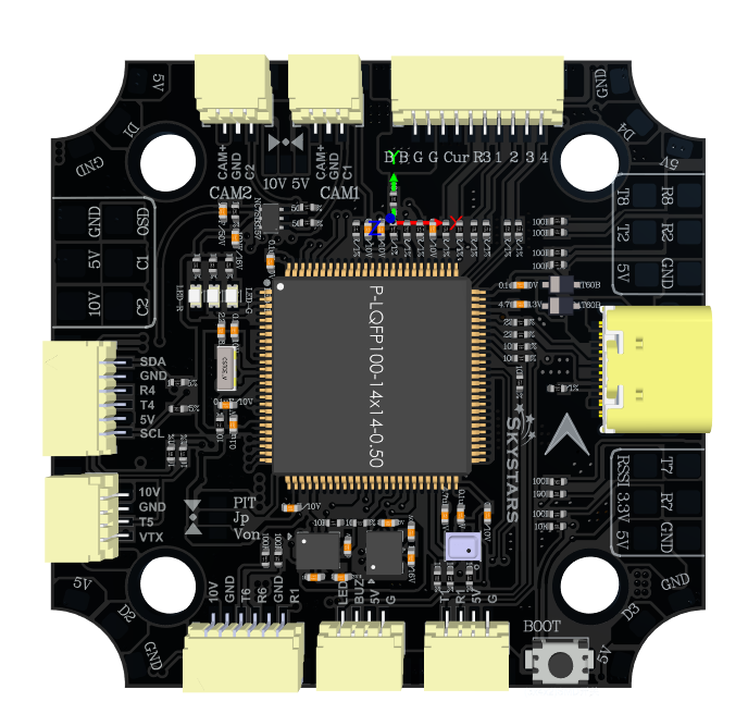
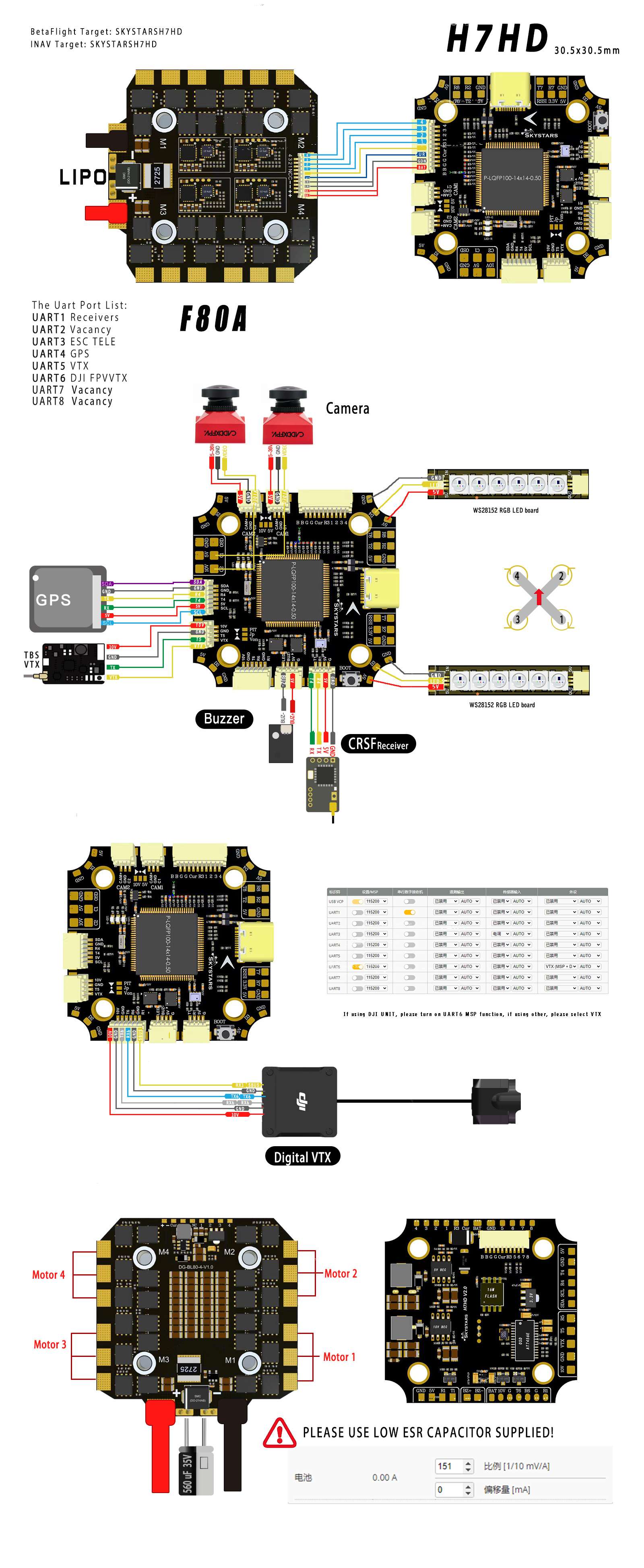
UART Mapping
The UARTs are marked Rn and Tn in the above pinouts. The Rn pin is the receive pin for UARTn. The Tn pin is the transmit pin for UARTn.
SERIAL0 -> USB
SERIAL1 -> UART1 (RCin, DMA-enabled)
SERIAL2 -> UART2 (MAVLink2 DMA-enabled)
SERIAL3 -> UART3 (ESC Telem)
SERIAL4 -> UART4 (GPS, DMA-enabled)
SERIAL5 -> UART5 (SmartAudio)
SERIAL6 -> UART6 (DisplayPort, DMA-enabled)
SERIAL7 -> UART7 (USER DMA-enabled)
SERIAL8 -> UART8 (USER)
RC Input
The default RC input is configured on the UART1 (R1). Unidirectional serial inputs can be directly tied to R1 . Bi-directional protocols require connection to T1 in addition:
PPM is not supported.
SBUS/DSM/SRXL connects to the R1 pin.
FPort requires connection to T1. Set SERIAL1_OPTIONS = 7
CRSF/ELRS also requires both T1 and R1 connections and provides telemetry automatically.
OSD Support
By default, Skystars H7HDV2 supports OSD using OSD_TYPE 1 (MAX7456 driver) and simultaneously DisplayPort using UART6 on the HD VTX connector.
PWM Output
The Skystars H7HDV2 supports up to 9 PWM outputs. The pads for motor output M1 to M8 on the two motor connectors, plus M9 for LED strip, by default, or another PWM output.
The PWM is in 5 groups:
PWM 1, 2 in group1
PWM 3, 4 in group2
PWM 5-8 in group3
PWM 9 in group4
Channels within the same group need to use the same output rate. If any channel in a group uses DShot then all channels in the group need to use DShot. Outputs 1-8 support bi-directional dshot.
Battery Monitoring
The board has a builtin voltage and current sensor. The current sensor can read up to 130 Amps. The voltage sensor can handle up to 6S LiPo batteries.
The correct battery setting parameters are:
BATT_MONITOR = 4
BATT_VOLT_PIN = 10
BATT_CURR_PIN = 11 (CURR pin)
BATT_VOLT_MULT = 10.1
BATT_AMP_PERVLT = 17.0
Compass
The Skystars H7HDV2 does not have a builtin compass, but you can attach an external compass using I2C on the SDA and SCL pads.
VTX power control
If the JP jumper is bridged to PIT then GPIO 81 controls the VTX BEC output to pins marked “10V” and is included on the HD VTX connector. Setting this GPIO low removes voltage supply to this pin/pad. RELAY2 is configured by default to control this GPIO and is high by default.
Camera control
GPIO 82 controls the analogue camera outputs. Setting this GPIO high selects Camera 1, low selects Camera 2. RELAY3 is configured by default to control this GPIO and is high by default.
RSSI
For analog RSSI set RSSI_TYPE to “1” and RSSI_ANA_PIN to “13”. For RC protocols that report RSSI, set RSSI_TYPE to “3”.
Additional GPIO
GPIO 83 is marked as “OSD”. It can be used as a general GPIO pin. By default RELAY4 is configured to control this pin and sets the GPIO high at boot.
Loading Firmware
Firmware for these boards can be found here in sub-folders labeled “SkystarsH7HDV2”.
Initial firmware load can be done with DFU by plugging in USB with the bootloader button pressed. Then you should load the “with_bl.hex” firmware, using your favourite DFU loading tool.
Once the initial firmware is loaded you can update the firmware using any ArduPilot ground station software. Updates should be done with the *.apj firmware files.