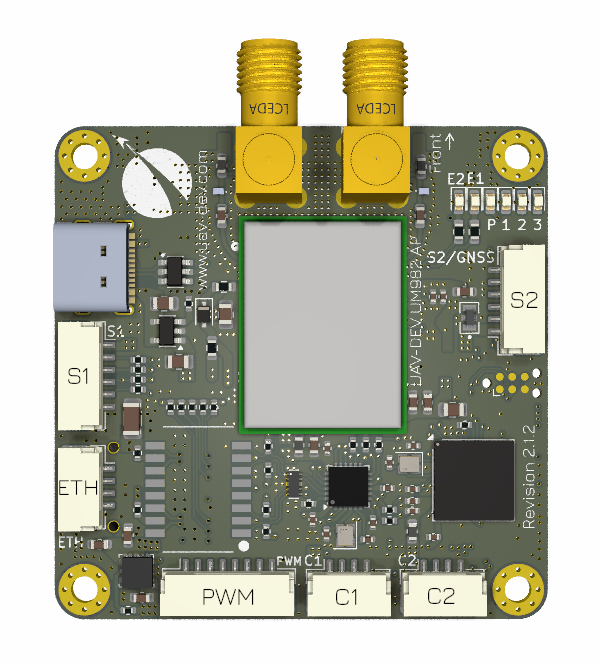
UAV-DEV-FC-UM982
The UAV-DEV-FC-UM92 Flight Controller integrates an RTK GNSS module capable of producing compass-less heading when using a dual antenna configuration and is sold by UAV-DEV GmbH Webshop
Features
- Processor
STM32H743
480MHz
2MB Flash
1MB RAM
- Sensors
IMU TDK Invensense ICM-45686
Barometer Infineon DPS310
Magnetometer Bosch BMM150
GNSS Unicore UM982 L1/L2/L5 RTK GNSS with GNSS Heading
- Power
5.2V input via JST-GH
- Interfaces
USB-C
100 MBits/s Ethernet
6 x PWM / DShot, 2 x Bidirectional-DShot capable
RC Input
6 UARTs, 4 available externally
2 x FD CAN ports with 120 Ohm termination resistor
microSD
DEBUG
- Physical
Size: 50mm x 50mm (without SMA connector) x 15mm
Weight: 22g with microSD card
Pinout
S1 - SERIAL4 & SERIAL5 - 6 Pin JST-GH
Pin |
Signal Name |
Voltage |
|---|---|---|
1 |
+5V |
5V |
2 |
USART6_TX |
3.3V |
3 |
USART6_RX |
3.3V |
4 |
UART7_TX |
3.3V |
5 |
UART7_RX |
3.3V |
6 |
GND |
GND |
PWM - PWM / DShot / Telemetry - 8 Pin JST-GH
Pin |
Signal Name |
Voltage |
|---|---|---|
1 |
PWM / DShot 1 BIDIR |
3.3V |
2 |
PWM / DShot 2 BIDIR |
3.3V |
3 |
PWM / DShot 3 BIDIR |
3.3V |
4 |
PWM / DShot 4 BIDIR |
3.3V |
5 |
PWM / DShot 5 |
3.3V |
6 |
PWM / DShot 6 |
3.3V |
7 |
USART3_RX / TELEM |
3.3V |
8 |
GND |
GND |
C1 - CAN FD 1 - 4 Pin JST-GH
Pin |
Signal Name |
Voltage |
|---|---|---|
1 |
+5V |
5V |
2 |
CAN_H |
|
3 |
CAN_L |
|
4 |
GND |
GND |
C2 - CAN FD 2 - 4 Pin JST-GH
Pin |
Signal Name |
Voltage |
|---|---|---|
1 |
+5V |
5V |
2 |
CAN_H |
|
3 |
CAN_L |
|
4 |
GND |
GND |
Debug - 6 Pin Tag-Connect
Pin |
Signal Name |
Voltage |
|---|---|---|
1 |
+3.3V |
3.3V |
2 |
SWDIO |
3.3V |
3 |
NRST |
3.3V |
4 |
SWCLK |
3.3V |
5 |
GND |
GND |
6 |
not connected |
S2 - SERIAL1 & GNSS - 6 Pin JST-GH
Pin |
Signal Name |
Voltage |
|---|---|---|
1 |
+5V |
5V |
2 |
USART1_TX |
3.3V |
3 |
USART1_RX |
3.3V |
4 |
GNSS_PPS |
3.3V |
5 |
GNSS_EVENT |
3.3V |
6 |
GND |
GND |
ETH - Ethernet - 4 Pin JST-GH
Pin |
Signal Name |
|---|---|
1 |
RX- |
2 |
RX+ |
3 |
TX- |
4 |
TX+ |
UART Mapping
Name |
Function |
|---|---|
SERIAL0 |
USB |
SERIAL1 |
USART1 (MAVLink) |
SERIAL2 |
UART8 (GPS1) Internal: GNSS UM982 module |
SERIAL3 |
USART2 (Scripting) Internal: GNSS UM9892 module |
SERIAL4 |
USART6 (RCIN) |
SERIAL5 |
UART7 (MAVLink) |
SERIAL6 |
USART3 (ESC telemetry) |
SERIAL7 |
OTG2 (SLCAN) |
All UARTs except USART3 TX have DMA capability. Any UART can be re-tasked by changing its protocol parameter.
RC Input
RC input is configured on connector S1 / SERIAL4 / UART6. Unidirectional protocols such as SBUS and DSM connect to RX6
PPM not supported
CRSF would require SERIAL4_OPTIONS set to “0”.
SRXL2 would require SERIAL4_OPTIONS set to “4”. And only connect the TX6 pin.
Battery Monitoring
Pre-configured to use DroneCAN with the supplied UAV-DEV-POWERMODULE
Compass
The autopilot includes an internal compass as well as GNSS-based heading, but GNSS-based heading is the recommended heading source, in which case, the internal compass should be disabled or set as a lower priority. Proper setup and placement of the dual antennas is required as well as setup of the moving baseline parameters, see GPS for Yaw (aka Moving Baseline) for more details.
Motor Output
All outputs are capable of PWM and DShot. Motors 1 through 4 are capable of Bidirectional-DShot. All outputs in the motor groups below must be the same protocol:
Motors 1-4 Group1 (TIM4)
Motors 5-6 Group2 (TIM3)
Firmware
Firmware for this board can be found here in sub-folders labeled “uav-dev-fc-um982”.
Loading Firmware
This autopilot comes with ArduPilot compatible bootloader. You can update the firmware using any ArduPilot ground station software. Later updates should be done with the “*.apj” firmware files.