RadiolinkPIX6 Flight Controller

Featuring STM32F7 cpu, vibration isolation of IMUs, redundant IMUs, integrated OSD chip, IMU heating, and DShot.
Specifications
Processor
32-bit ARM Cortex M7 core with DPFPU - STM32F765VIT6
216 MHz/512 KB RAM/2 MB Flash
32-bit IOMCU co-processor - STM32F100
32KB FRAM - FM25V02A
AT7456E OSD
Sensors
Bosh BMI088 IMU (accel, gyro)
InvenSense ICM-42688 IMU (accel, gyro)
SPL06 barometer
IST8310 magnetometer
Power
SMBUS/I2C Power Module Inputs(I2C)
voltage and current monitor inputs(Analog)
Interfaces
16 PWM Outputs with independent power rail for external power source
5x UART serial ports, 2 with HW flow control
Camera Input and Video Output
PPM/SBUS input, DSM/SBUS input
RSSI (PWM or voltage) input
I2C, SPI, 2x CAN, USB
3.3V and 6.6V ADC inputs
Buzzer and Safety Switch
microSD card
Physical
Weight 80g
Size 94mm x 51.5mm x 14.5mm
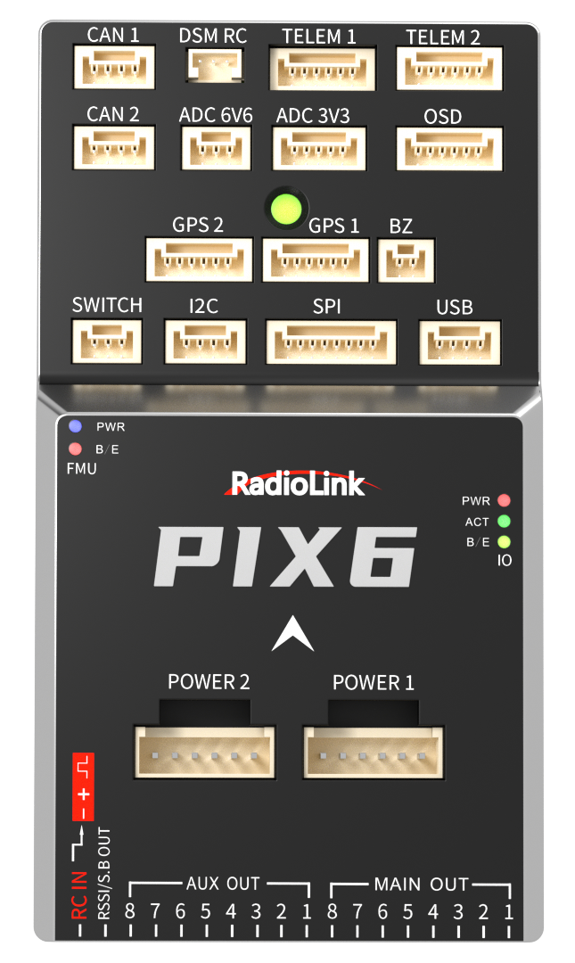
Connector assignments
Top View
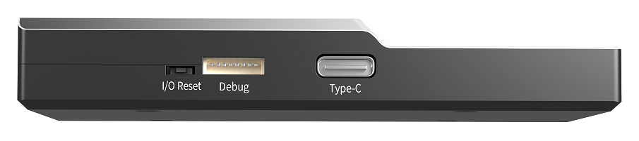
Left View

Right View
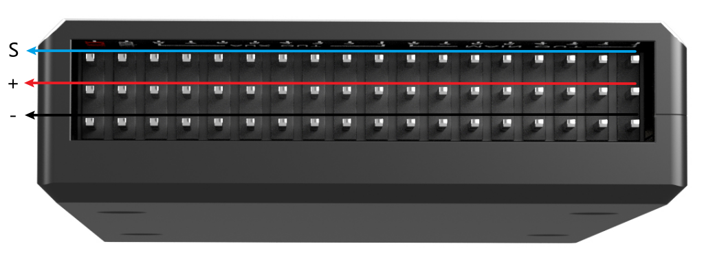
Rear View
Pinouts
TELEM1, TELEM2 ports
Pin |
Signal |
Volt |
|---|---|---|
1 |
VCC |
+5V |
2 |
TX(OUT) |
+3.3V |
3 |
RX(IN) |
+3.3V |
4 |
CTS |
+3.3V |
5 |
RTS |
+3.3V |
6 |
GND |
GND |
OSD
Pin |
Signal |
Volt |
|---|---|---|
1 |
GND |
GND |
2 |
VOUT |
+3.3V |
3 |
VCC |
+5V |
4 |
GND |
GND |
5 |
VCC |
+5V |
6 |
VIN |
+3.3V |
I2C port
Pin |
Signal |
Volt |
|---|---|---|
1 |
VCC |
+5V |
2 |
SCL |
+3.3V (pullups) |
3 |
SDA |
+3.3V (pullups) |
4 |
GND |
GND |
CAN1, CAN2 ports
Pin |
Signal |
Volt |
|---|---|---|
1 |
VCC |
+5V |
2 |
CAN_H |
+12V |
3 |
CAN_L |
+12V |
4 |
GND |
GND |
GPS1 port
Pin |
Signal |
Volt |
|---|---|---|
1 |
VCC |
+5V |
2 |
TX(OUT) |
+3.3V |
3 |
RX(IN) |
+3.3V |
4 |
SCL |
+3.3V |
5 |
SDA |
+3.3V |
6 |
GND |
GND |
GPS2 Port
Pin |
Signal |
Volt |
|---|---|---|
1 |
VCC |
+5V |
2 |
TX(OUT) |
+3.3V |
3 |
RX(IN) |
+3.3V |
4 |
SCL |
+3.3V |
5 |
SDA |
+3.3V |
6 |
GND |
GND |
SPI
Pin |
Signal |
Volt |
|---|---|---|
1 |
VCC |
+5V |
2 |
SPI_SCK |
+3.3V |
3 |
SPI_MISO |
+3.3V |
4 |
SPI_MOSI |
+3.3V |
5 |
!SPI_NSS1 |
+3.3V |
6 |
!SPI_NSS2 |
+3.3V |
7 |
DRDY |
+3.3V |
8 |
GND |
GND |
POWER1
Pin |
Signal |
Volt |
|---|---|---|
1 |
VCC |
+5V |
2 |
VCC |
+5V |
3 |
CURRENT |
up to +3.3V |
4 |
VOLTAGE |
up to +3.3V |
5 |
GND |
GND |
6 |
GND |
GND |
POWER2
Pin |
Signal |
Volt |
|---|---|---|
1 |
VCC |
+5V |
2 |
VCC |
+5V |
3 |
SCL |
+3.3V |
4 |
SDA |
+3.3V |
5 |
GND |
GND |
6 |
GND |
GND |
ADC 3.3V
Pin |
Signal |
Volt |
|---|---|---|
1 |
VCC |
+5V |
2 |
ADC IN1 |
up to +3.3V |
3 |
GND |
GND |
4 |
ADC IN2 |
up to +3.3v |
5 |
GND |
GND |
ADC 6.6V
Pin |
Signal |
Volt |
|---|---|---|
1 |
VCC |
+5V |
2 |
ADC IN |
up to 6.6V |
3 |
GND |
GND |
USB remote port
Pin |
Signal |
Volt |
|---|---|---|
1 |
USB VDD |
+5V |
2 |
DM |
+3.3V |
3 |
DP |
+3.3V |
4 |
GND |
GND |
SWITCH
Pin |
Signal |
Volt |
|---|---|---|
1 |
VCC |
+3.3V |
2 |
!IO_LED_SAFETY |
GND |
3 |
SAFETY |
GND |
Buzzer port
Pin |
Signal |
Volt |
|---|---|---|
1 |
VCC |
+5V |
2 |
BUZZER- |
+5V |
Spektrum/DSM Port
Pin |
Signal |
Volt |
|---|---|---|
1 |
VCC |
+3.3V |
2 |
GND |
GND |
3 |
Signal |
+3.3V |
Debug port
Pin |
Signal |
Volt |
|---|---|---|
1 |
VCC |
+5V |
2 |
FMU_SWCLK |
+3.3V |
3 |
FMU_SWDIO |
+3.3V |
4 |
TX(UART7) |
+3.3V |
5 |
RX(UART7) |
+3.3V |
6 |
IO_SWCLK |
+3.3V |
7 |
IO_SWDIO |
+3.3V |
8 |
GND |
GND |
UART Mapping
SERIAL0 -> USB
SERIAL1 -> USART2 (Telem1) RTS/CTS pins, RX DMA capable
SERIAL2 -> USART3 (Telem2) RTS/CTS pins, TX/RX DMA capable
SERIAL3 -> USART1 (GPS1), TX/RX DMA capable
SERIAL4 -> UART4 (GPS2), No DMA
SERIAL5 -> UART7 (User), No DMA
RC Input
The RCIN pin, which by default is mapped to a timer input, can be used for all ArduPilot supported receiver protocols, except CRSF/ELRS and SRXL2 which require a true UART connection. However, FPort, when connected in this manner, will only provide RC without telemetry.
To allow CRSF and embedded telemetry available in Fport, CRSF, and SRXL2 receivers, a full UART with DMA capability, such as SERIAL1 (USART2) would need to be used for receiver connections. Below are setups using Serial6.
SERIAL1_PROTOCOL should be set to “23”.
FPort would require SERIAL1_OPTIONS be set to “15”.
CRSF would require SERIAL1_OPTIONS be set to “0”.
SRXL2 would require SERIAL1_OPTIONS be set to “4” and connects only the TX pin.
Any UART can be used for RC system connections in ArduPilot also, and is compatible with all protocols except PPM. See Radio Control Systems for details.
OSD Support
The RadiolinkPIX6 support using its internal OSD using OSD_TYPE 1 (MAX7456 driver). External OSD support such as DJI or DisplayPort is supported using UART3 or any other free UART. See MSP OSD for more info.
PWM Outputs
The RadiolinkPIX6 supports up to 16 PWM outputs. All 16 outputs support all normal PWM output formats. All FMU (“AUX OUT”) outputs also support DShot.
The 8 FMU PWM outputs are in 4 groups:
Outputs 1, 2, 3 and 4 in group1
Outputs 5 and 8 in group2
Outputs 6 and 7 in group3
FMU outputs within the same group need to use the same output rate and protocol, ie. if any output in a group uses DShot then all channels in that group need to use DShot.
Battery Monitoring
The board has 2 dedicated power monitor ports with a 6 pin connector. One is the Analog power monitor(Power1), and the others is the I2C power monitor(Power2).
Power1 port(Analog)
The parameters should be set:
BATT_MONITOR = 4, then reboot.
BATT_VOLT_PIN = 2
BATT_CURR_PIN = 5
BATT_VOLT_MULT = 18
BATT_AMP_PERVLT = 24
Power2 port(I2C)
The parameters should be set.:
BATT2_MONITOR = 21
BATT2_I2C_BUS = 1
BATT2_I2C_ADDR = 65
Compass
The RadiolinkPIX6 has a built-in compass. Due to potential interference, the autopilot is usually used with an external I2C compass as part of a GPS/Compass combination.
Analog inputs
The RadiolinkPIX6 has 3 analog inputs, one 6V tolerant and two 3.3V tolerant
ADC Pin12 -> ADC 6.6V Sense
ADC Pin4 -> ADC IN1 3.3V Sense
ADC Pin13 -> ADC IN2 3.3V Sense
Analog 3.3V RSSI input pin = 103
Connectors
Unless noted otherwise all connectors are JST GH
Firmware
Firmware for this board can be found here in sub-folders labeled “RadiolinkPIX6”.
Loading Firmware
The board comes pre-installed with an ArduPilot compatible bootloader, allowing the loading of xxxxxx.apj firmware files with any ArduPilot compatible ground station.