MicoAir743v2
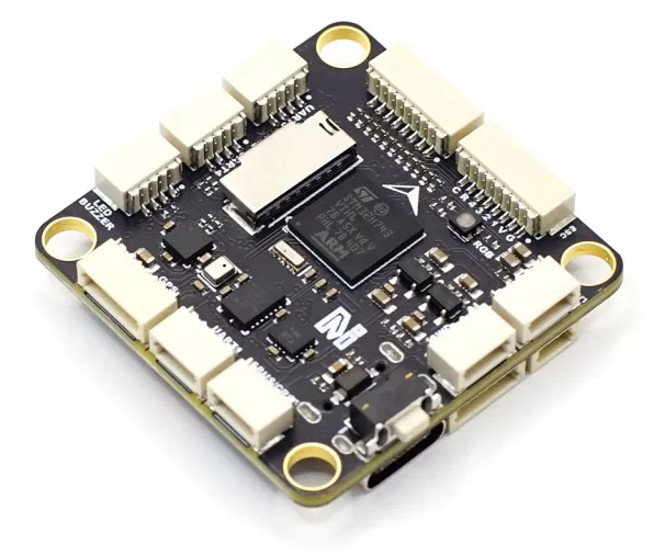
The MicoAir743v2 is a flight controller designed and produced by MicoAir Tech.
Features
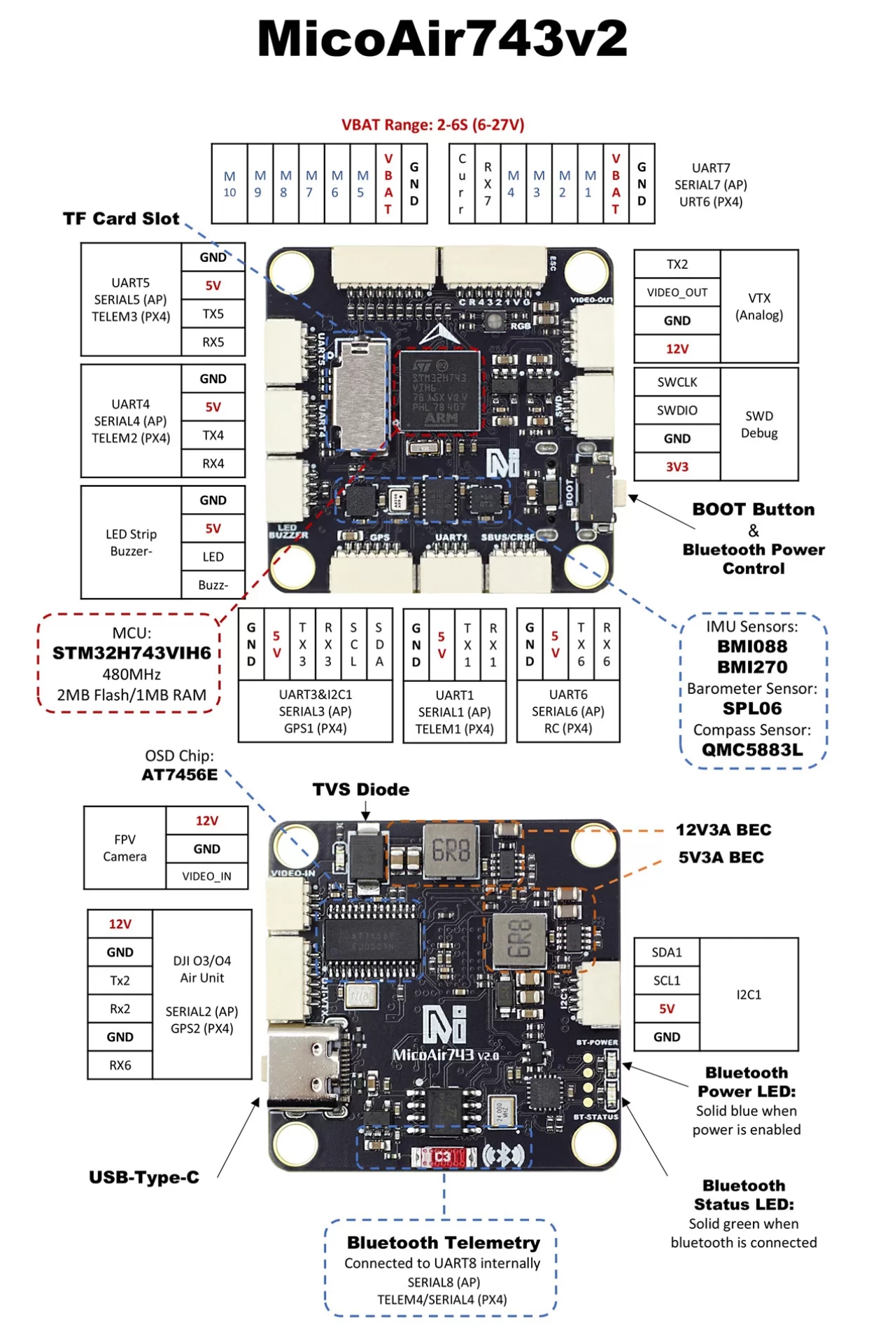
STM32H743 microcontroller
BMI088/BMI270 dual IMUs
Integrated BlueTooth module for telemetry
SPL06 barometer
QMC5883L magnetometer
AT7456E OSD
9V 3A BEC; 5V 3A BEC
MicroSD Card Slot
8 UARTs
11 PWM outputs
1 I2C
1 SWD
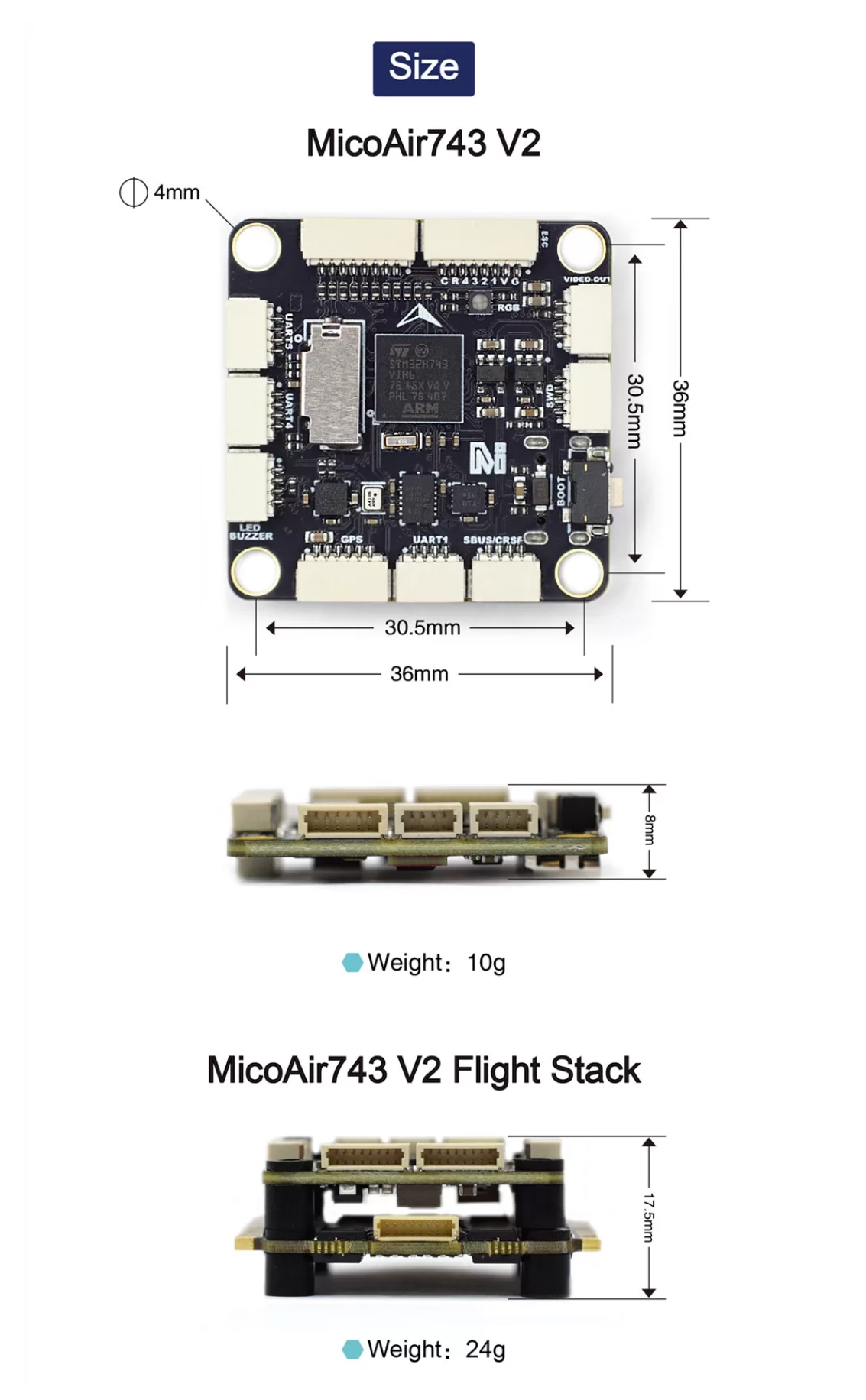
Physical
Pinout
UART Mapping
SERIAL0 -> USB
SERIAL1 -> UART1 (MAVLink2, DMA-enabled)
SERIAL2 -> UART2 (DisplayPort, DMA-enabled)
SERIAL3 -> UART3 (GPS, DMA-enabled)
SERIAL4 -> UART4 (MAVLink2, DMA-enabled)
SERIAL5 -> UART5 (User, DMA-enabled)
SERIAL6 -> UART6 (RCIN, DMA-enabled)
SERIAL7 -> UART7 (RX only, ESC Telemetry, DMA-enabled)
SERIAL8 -> UART8 (MAVLink2, connected to on board BlueTooth module)
RC Input
The UART6 is compatible with all ArduPilot supported receiver protocols.
PPM is not supported.
SBUS/DSM/SRXL connects to the RX6 pin.
FPort requires connection to TX6 . See FPort Receivers.
CRSF also requires a TX6 connection, in addition to RX6, and automatically provides telemetry.
SRXL2 requires a connection to TX6 and automatically provides telemetry. Set SERIAL6_OPTIONS to “4”.
Any UART can also be used for RC system connections in ArduPilot and is compatible with all protocols except PPM. See Radio Control Systems for details.
OSD Support
The MicoAir743v2 supports onboard OSD using OSD_TYPE 1 (MAX7456 driver). Simultaneously, DisplayPort OSD is available on the HD VTX connector, set OSD_TYPE2 = “5”.
VTX Support
The SH1.0-6P connector supports a DJI Air Unit / HD VTX connection. Protocol defaults to DisplayPort. Pin 1 of the connector is 9v so be careful not to connect this to a peripheral requiring 5v.
PWM Output
The MicoAir743v2 supports up to 11 PWM outputs. All the channels support DShot. Channels 1-8 support bi-directional DShot.
PWM outputs are grouped and every group must use the same output protocol:
1, 2, 3, 4 are Group 1
5, 6 are Group 2
7, 8, 11 are Group 3
9, 10 are Group 4
Note: PWM11 is the “LED” pin. If this is configured for serial LED use then PWM 7 and 8 can only be used as serial LED also.
Battery Monitoring
The board has a internal voltage sensor and connections on the ESC connector for an external current sensor input. The voltage sensor can handle up to 6S LiPo batteries.
The default battery parameters are:
BATT_MONITOR = 4
BATT_VOLT_PIN = 10
BATT_VOLT_MULT = 21.12
BATT_CURR_PIN = 11
BATT_AMP_PERVLT = 40.2
Compass
The MicoAir743v2 has a built-in compass. Due to potential interference, the autopilot is usually used with an external I2C compass as part of a GPS/Compass combination and the internal compass disabled.
BlueTooth
The MicoAir743v2 has an on board BlueTooth module connected to UART8(SERIAL8). The BlueTooth id is MicoAir743v2-xxxxxx and you can connect to it without pairing id.
Firmware
Firmware for this board can be found here in sub-folders labeled “MicoAir743v2”
Loading Firmware
Initial firmware load can be done with DFU by plugging in USB with the bootloader button pressed. Then you should load the “arduXXXX_with_bl.hex” firmware, using your favorite DFU loading tool.
Once the initial firmware is loaded you can update the firmware using any ArduPilot ground station software. Updates should be done with the “*.apj” firmware files.