SPEDIX H743
The SPEDIX H743 is a flight controller based on the STM32H743 MCU.
Features
MCU - STM32H743 32-bit processor running at 480 MHz
IMU - Dual ICM42688
Barometer - SPL06
OSD - MAX7456
8x UARTs
CAN support
9x PWM Outputs (8 Motor Output, 1 LED)
Battery input voltage: 2S-6S
BEC 3.3V 0.5A
BEC 5V 3A
BEC 12V 3A for video, gpio controlled
Dual camera inputs with switching support
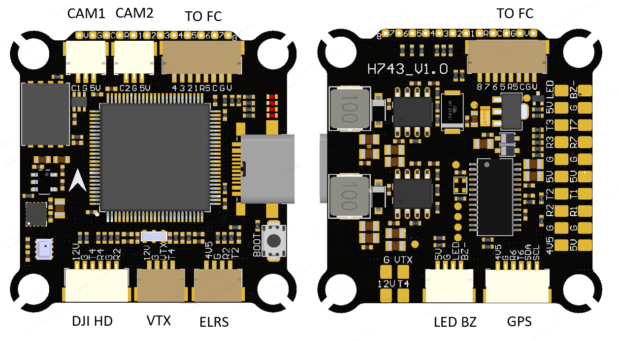
Pinout
UART Mapping
SERIAL0 -> USB
SERIAL1 -> UART1 (Telem 1, DMA-enabled)
SERIAL2 -> UART2 (RC Input, DMA-enabled)
SERIAL3 -> UART3 (Telem 2, DMA-enabled)
SERIAL4 -> UART4 (MSP DisplayPort, DMA-enabled)
SERIAL5 -> UART5 (ESC Telemetry)
SERIAL6 -> UART6 (GPS, DMA-enabled)
SERIAL7 -> UART7 (Spare)
SERIAL8 -> UART8 (OTG2)
RC Input
RC input is configured by default via the USART2. It supports all serial RC protocols except PPM.
FPort: the receiver must be also tied to the USART2 TX pin , RSSI_TYPE set to 3, and SERIAL2_OPTIONS must be set to 7 (invert TX/RX, half duplex).
CRSF/ELRS use both RX2 and TX2 and set RSSI_TYPE to 3.
OSD Support
Onboard OSD using OSD_TYPE 1 (MAX7456 driver) is supported by default. Simultaneously, DisplayPort OSD is available on the HD VTX connector.
PWM Output
The SPEDIX F405 supports up to 9 PWM outputs. The pads for motor output M1 to M8 are provided on both the motor connectors and on separate pads, plus M9 on a separate pad for LED strip (default configuration) or another PWM output.
The PWM is in 4 groups:
PWM 1-4 in group1
PWM 5-6 in group2
PWM 7-8 in group3
PWM 9 in group4
Channels within the same group need to use the same output rate. If any channel in a group uses DShot then all channels in the group need to use DShot. Channels 1-8 support bi-directional dshot.
Battery Monitoring
The board has a built-in voltage sensor and external current sensor input. The voltage sensor can handle up to 6S LiPo batteries. The correct battery setting parameters are:
BATT_MONITOR = 4
BATT_VOLT_PIN = 10
BATT_CURR_PIN = 11 (CURR pin)
BATT_VOLT_MULT = 11.0
BATT_AMP_PERVLT = 25 (depends on sensor used)
Compass
No onboard compass. Use external I2C compass via SDA/SCL pads.
VTX power control
GPIO 82 controls the VTX BEC output to pins marked “12V” and is included on the HD VTX connector. Setting this GPIO low removes voltage supply to this pin/pad. By default RELAY3 is configured to control this pin and sets the GPIO high.
Camera control
GPIO 83 controls the camera output to the connectors marked “CAM1” and “CAM2”. Setting this GPIO low switches the video output from CAM1 to CAM2. By default RELAY4 is configured to control this pin and sets the GPIO high.
Firmware
Firmware for the SPEDIX H743 is available from ArduPilot Firmware Server under the SPEDIXH743 target.
Loading Firmware
Use DFU (USB + BOOT button) to flash with_bl.hex for first time.
Use .apj files for subsequent updates via ground station.