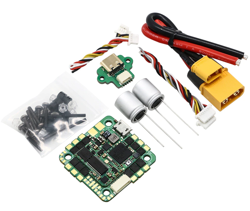
IFlight Blitz Whoop F7 AIO

the above image and some content courtesy of IFlight
Specifications
Processor
BGA-STM32F745, 216MHz
AT7456E OSD
16MB flash for datalogging
Integrated 55A 4in1 BLHeli_S / BlueJay ESC
Sensors
BMI270 IMU (accel, gyro)
DPS310 or SPL06 barometer
Voltage & 165A current sensor
Power
2S - 6S LiHV input voltage with voltage monitoring
55A Cont., 165A peak current monitor
5V, 2A BEC for internal and peripherals
Interfaces
5x PWM outputs, 4 Bi-Directionla DShot capable connected in onboard ESC + integrated NeoPixel LED on board(
4x UARTs/serial for GPS and other peripherals
I2C port for external compass, airspeed, etc.
USB-C port
Size and Dimensions
35mm x 35mm (25.5mm mounting pattern)
10.5g
Where to Buy
User Manual
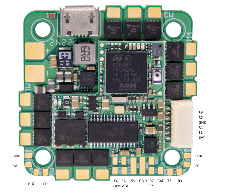
Pinout

Default UART order
The UARTs are marked Rn and Tn in the above pinouts. The Rn pin is the receive pin for UARTn. The Tn pin is the transmit pin for UARTn.
SERIAL0 -> USB
SERIAL1 -> USART1 (DJI connector, DJI Goggle OSD protocol) (DMA capable)
SERIAL2 -> USART2 (RX2 on DJI connector, protocol is for RC input) (DMA capable)
SERIAL3 -> USART3 (GPS) (DMA capable)
SERIAL4 -> UART4 (User)
SERIAL7 -> UART7 (User)
Serial protocols shown are defaults, but can be adjusted to personal preferences.
Servo/Motor Outputs
The BLITZ Whoop F7 AIO has 4 PWM outputs internally connected to its 4-in-1 ESC. The pads for motor output are M1 to M4 on the board. All 4 outputs support bi-directional DShot and DShot, as well as all PWM types. The default configuration is for bi-directional DShot using the already installed BlueJay firmware.
The PWM are in in two groups:
PWM 1-4 in group1
PWM 5 in group2
Note
for users migrating from BetaflightX quads, the first four outputs M1-M4 have been configured for use with existing motor wiring using these default parameters:
FRAME_CLASS = 1 (Quad)
FRAME_TYPE = 12 (BetaFlightX)
RC Input
RC input is configured by default on RX2 on the DJI connector and supports all single wire RC protocols (SBUS,DSM,etc.) except PPM. FPort, when connected in this manner, can provide RC but without telemetry.
CRSF/ELRS and SRXL2 require a full UART connection. You should use one with DMA for CRSF/ELRS. For example you could retask UART4 for GPS by setting SERIAL4_PROTOCOL = “5” (GPS), then use UART3 for RC input and set SERIAL3_PROTOCOL = “23”. Under this scenario:
CRSF also requires a TX3 connection, in addition to RX3, and automatically provides telemetry.
SRXL2 requires a connection to TX3 and automatically provides telemetry. Set SERIAL3_OPTIONS to “4”.
FPORT with telemetry could use this setup also, but connects only to TX3 and SERIAL3_OPTIONS would be set to “7”.
OSD Support
The Blitz Whoop F7 AIO supports analog video transmission using its internal OSD using OSD_TYPE 1 (MAX7456 driver). External OSD support such as DJI or DisplayPort is supported by default on USART1 RX/TX or any other free UART. See MSP OSD for more info.
Battery Monitor Configuration
These settings are set as defaults when the firmware is loaded (except BATT_AMP_PERVLT which needs to be changed from the default value). However, if they are ever lost, you can manually set the parameters:
Enable Battery monitor.
BATT_MONITOR =4
Then reboot.
BATT_VOLT_MULT 10.9
Connecting a GPS/Compass module
This board does not include a Compass and/or GPS so an external GPS/compass can be connected in order for autonomous modes to function.
NeoPixel LED
The board includes a NeoPixel LED on the underside which is pre-configured to output ArduPilot sequences. This is the fifth PWM output. Its connection is also available by the LED pad.
Loading ArduPilot onto the board
Initial firmware load can be done with DFU by plugging in USB with the boot button pressed. Then you should load the “with_bl.hex” firmware, see Loading Firmware onto boards without existing ArduPilot firmware.
Once the initial firmware is loaded you can update the firmware using any ArduPilot ground station software, see Loading Firmware.
Firmware
Firmware for this board can be found here in sub-folders labeled “BlitzF745AIO” n.