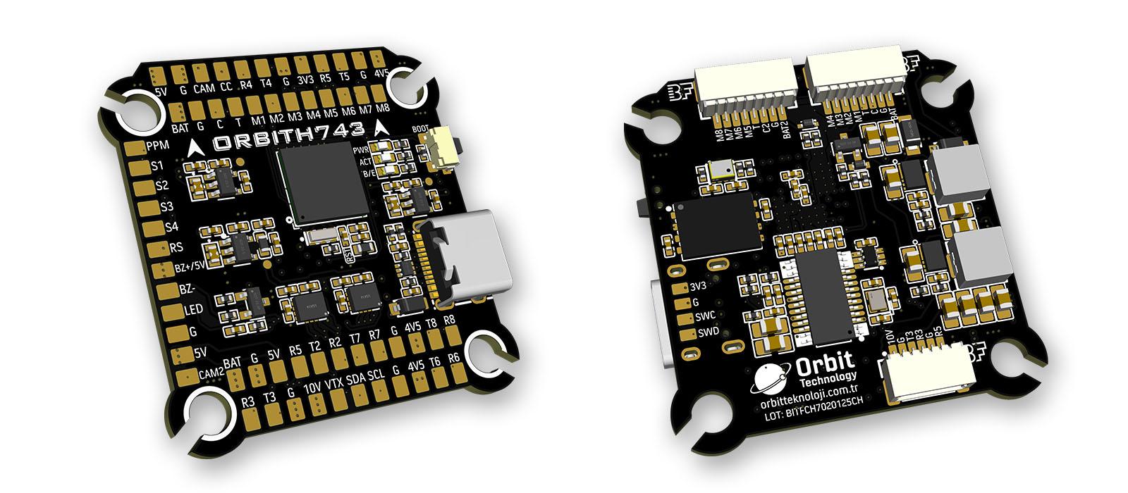
ORBITH743
The above image and some content courtesy of Orbit Technology-.
Specifications
Processor
STM32H743VIH6 (480MHz)
256MB Flash for data logging
Sensors
InvenSense 2x ICM42688 IMU (accel, gyro)
DPS368 barometer
Voltage & Current sensor
Power
2–6S LiPo input power
5V 3A BEC for peripherals
10V 3A BEC for video, GPIO controlled
Interfaces
USB Type-C port
8x UARTs
13x PWM outputs(one for serial LED by default) via two 8-pin ESC connectors and/or solder pads
1x RC input (PWM/SBUS)
I2C port for external compass, airspeed sensor, etc.
HD VTX support
Dual switchable analog Camera inputs
2x Power Monitor
Buzzer and LED strip
Built-in OSD
Size and Dimensions
38.3 mm x 39.8 mm
8.4 g
30.5 mm x 30.5 mm mounting holes
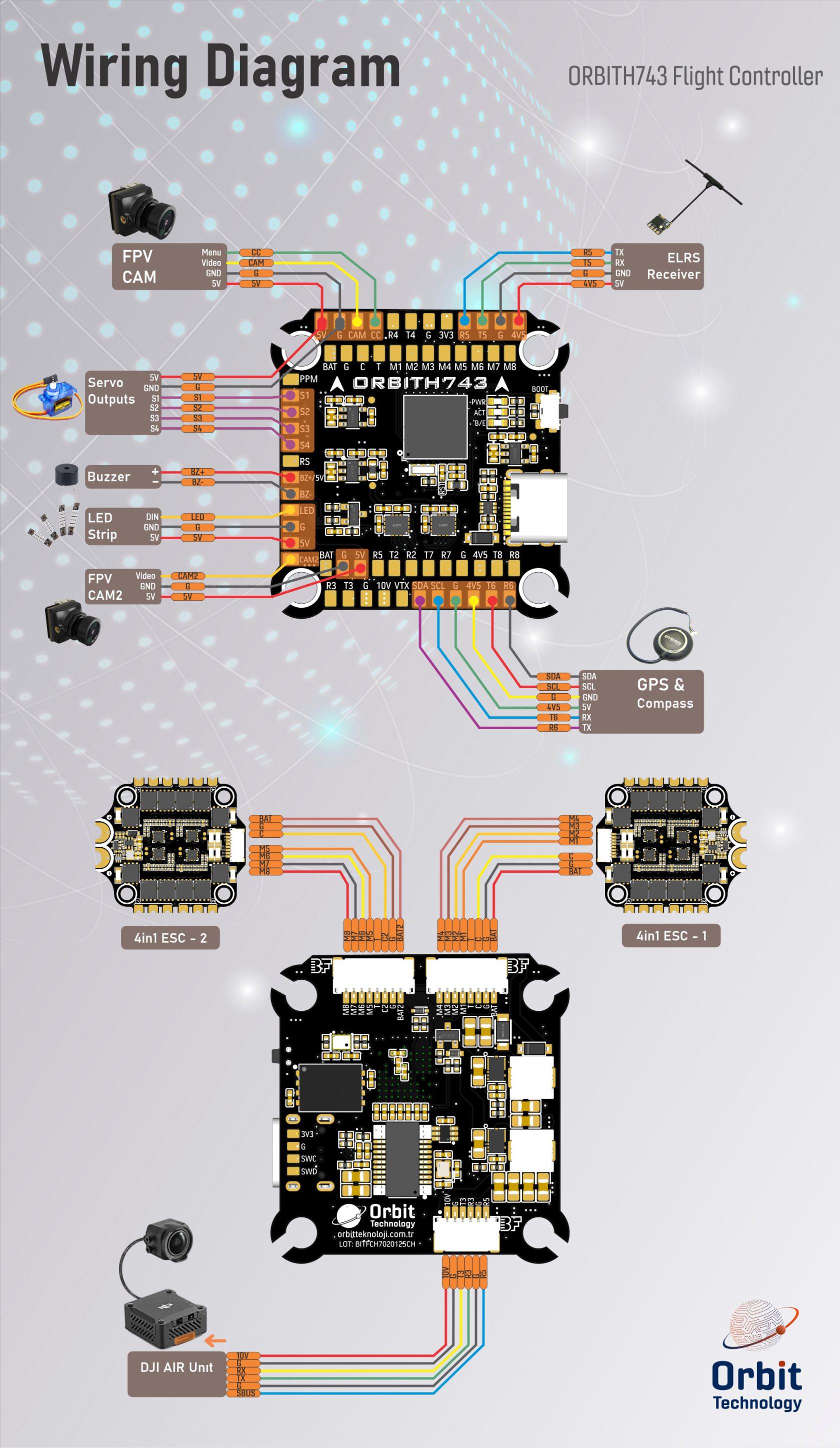
Wiring Diagram
UART Mapping
SERIAL0= USB (MAVLink2)SERIAL1= UART1 (ESC Telemetry)SERIAL2= UART2 (USER)SERIAL3= UART3 (DJI HD Air Unit)SERIAL4= UART4 (VTX)SERIAL5= UART5 (RC Input)SERIAL6= UART6 (GPS)SERIAL7= UART7 (USER)SERIAL8= UART8 (USER)
All UARTs have DMA capability except UART 1
Wiring Diagram
RC Input
RC input is configured by default on SERIAL5 (UART5). The 4V5 pin is powered by both USB and the onboard 5V BEC from the battery.
PPM is not supported. (PPM pin is not functional)
SBUS/DSM/SRXL connects to the RX5 pin.
FPort requires connection to TX5. Set SERIAL5_OPTIONS = 7
CRSF also requires both TX5 and RX5 connections and provides telemetry automatically.
Any UART can be used for RC system connections in ArduPilot. See the common RC systems documentation for details.
RSSI
Analog RSSI input is supported.
RSSI pin number: 8
Set RSSI_TYPE = 1 for analog RSSI, or = 3 for RSSI provided by RC protocols like CRSF.
OSD Support
The ORBITH743 has an onboard OSD using a MAX7456 chip and is enabled by default. The CAM1/2 and VTX pins provide connections for using the internal OSD. Simultaneous DisplayPort OSD is also possible and is configured by default.
DJI Video and OSD
An SH1.0 6P connector supports a standard HD VTX. SERIAL3 is configured by default for DisplayPort. Pin 1 provides 10V which is controlled by GPIO81 which is assigned to RELAY 2 by default. do not connect peripherals that cannot accept 10V to this pin.
DShot Capability
All motor outputs (M1–M8) support:
DShot
Bi-directional DShot (for BIDIR motors)
PWM
- Mixing DShot and PWM within the same timer group is not allowed. Groups must be uniformly configured. Output timer groups are:
1/2, 3/4, 5/6, 7/8.
Servo outputs (Outputs 9-12, marked S1–S4) on PA15, PB3, PD12, and PD13 (TIM2 and TIM4 timers) are PWM only. Output 13 (marked LED) is in a separate group and supports PWM/DShot or serial LED operation and is configured for serail LED operation by default.
GPIOs
ORBITH743 outputs can be used as GPIOs (relays, buttons, RPM, etc.). Set the SERVOx_FUNCTION = -1 to enable GPIO functionality.
GPIO Pin Mapping
PWM1 → 50
PWM2 → 51
PWM3 → 52
PWM4 → 53
PWM5 → 54
PWM6 → 55
PWM7 → 56
PWM8 → 57
PWM9 → 58
PWM10 → 59
PWM11 → 60
PWM12 → 61
LED → 62
BUZZER → 80
VTX PWR → 81 (internal)
CAM SW→ 82 (internal)
Camera Switch Control
GPIO 82 controls camera switching between the CAM and CAM2 inputs. Set high or low to toggle between analog camera inputs. RELAY3 is configured by default to control this GPO.
The “CC” pin is not functional.
Compass
This board does not include a compass. An external compass may be connected via the SCL/SA pins for autonomous features.
Battery Monitor
The autopilot can support up to two external analog battery monitors. The first monitor is enabled by default with these parameters:
BATT_MONITOR = 4
Then reboot.
First battery monitor is enabled by default:
BATT_VOLT_PIN = 10
BATT_CURR_PIN = 11
BATT_VOLT_MULT = 10.1
BATT_AMP_PERVLT = 80.0 (Calibrate as needed, depending on current sensor.)
The second battery monitor is not enabled by default, but its parameter defaults have been set:
BATT2_VOLT_PIN = 4
BATT2_CURR_PIN = 18
BATT2_VOLT_MULT = 10.1
BATT2_AMP_PERVLT = 80.0 (Calibrate as needed, depending on current sensor)
Where to Buy
Firmware
This board does not ship with ArduPilot pre-installed.
Follow this guide to load it for the first time.
Firmware can be found in ArduPilot firmware repo under the ORBITH743 sub-folder.