Droneer F405 Flight Controller
The Droneer F405 is a flight controller produced by Droneer.
Features
STM32F405 microcontroller
ICM42688-P IMU
max7456 OSD
5 UARTs
9 PWM outputs
Dual Camera inputs
3S to 8S LIPO operation
5V,3A BEC, 10V,2A VTX BEC
Physical: 37x37mm, 7g
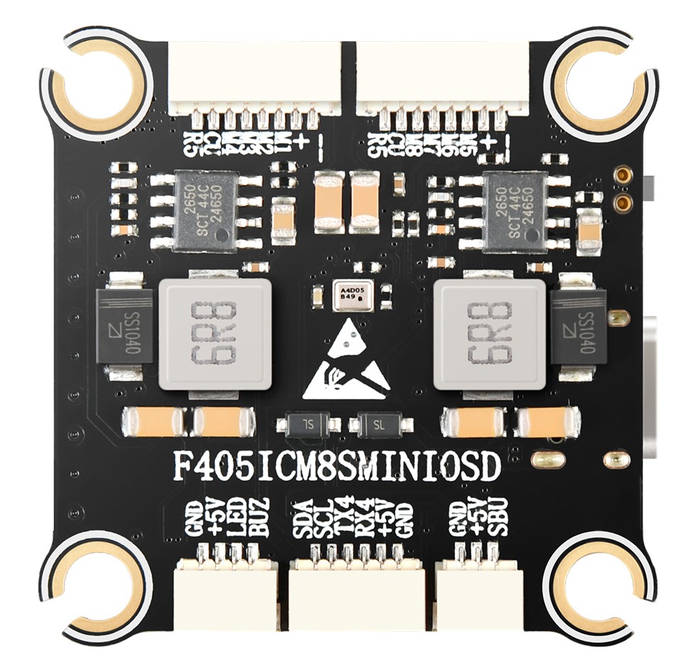
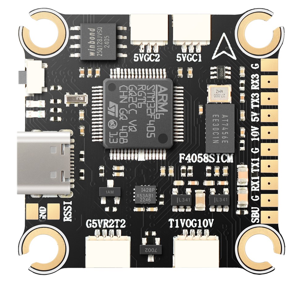
Pinout
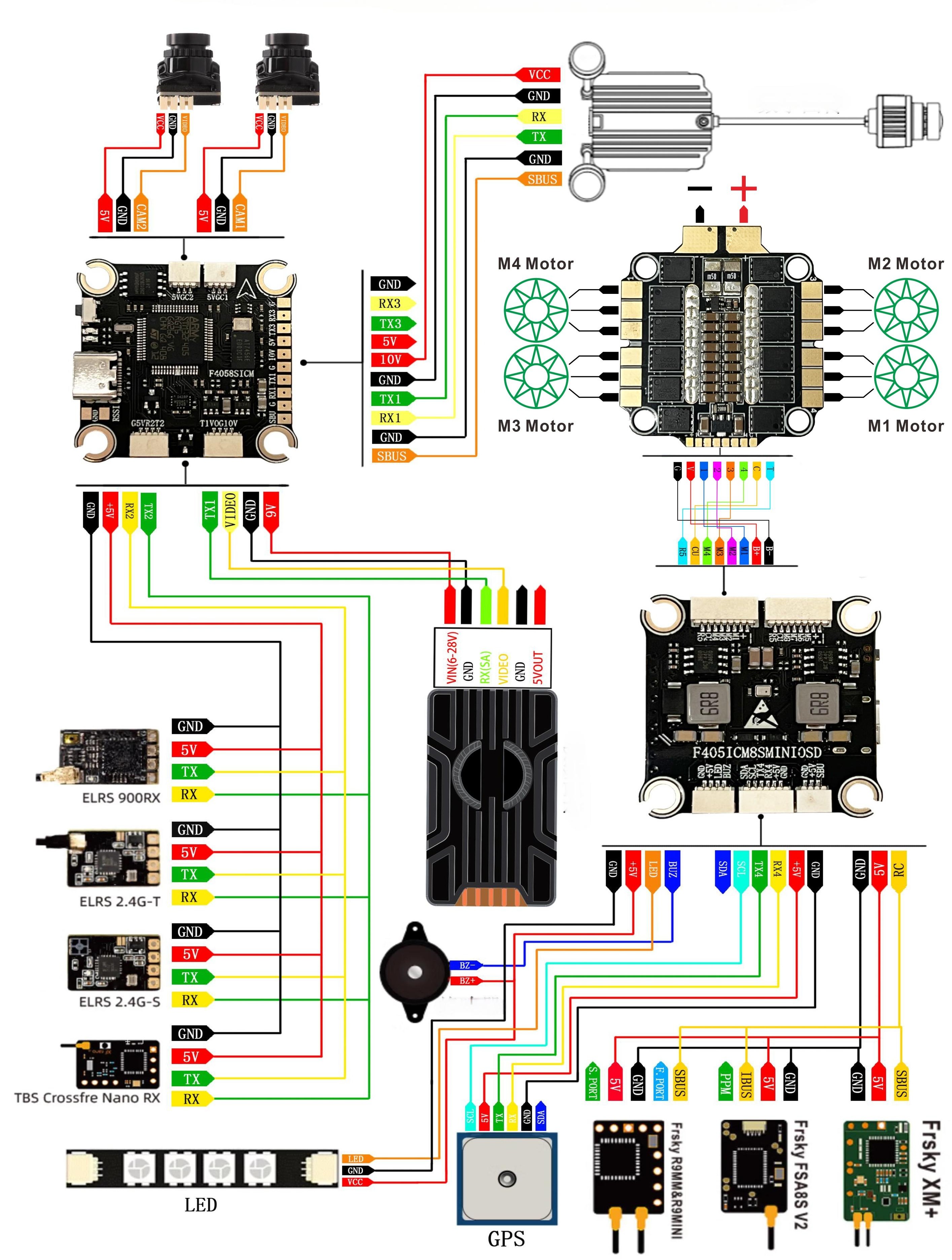
Typical Wiring Diagram
UART Mapping
The UARTs are marked Rn or RXn and Tn or TXn in the above pinouts. The Rn pin is the receive pin for UARTn. The Tn pin is the transmit pin for UARTn.
SERIAL0 -> USB
SERIAL1 -> UART1 (Tramp)
SERIAL2 -> UART2 (RCIN, DMA-enabled)
SERIAL3 -> UART3 (User)
SERIAL4 -> UART4 (GPS)
SERIAL5 -> UART5 (ESC Telem, RX5(only)on ESC connector)
Serial protocols shown are defaults, but can be adjusted to personal preferences.
RC Input
The SBUS pin (SBU), is passed by an inverter to RX2 (UART2 RX), which can be used for all ArduPilot supported receiver protocols, except PPM, CRSF/ELRS, and SRXL2. CRSF/ELRS and SRXL2 require the RX2 and TX2s pin be connected instead of the SBUS pin.
SRXL2 requires SERIAL2_OPTIONS be set to “4”.
Fport should be connected to TX2 via a bi-directional inverter and SERIAL2_OPTIONS be set to “4”. See Connecting to FrSky Sport and FPort.
Any UART can also be used for RC system connections in ArduPilot and is compatible with all protocols except PPM (SBUS requires external inversion on other UARTs). See Radio Control Systems for details.
FrSky Telemetry
FrSky Telemetry is supported using the Tx pin of any UART. You need to set the following parameters to enable support for FrSky S.PORT (example shows SERIAL3).
SERIAL3_PROTOCOL = 10
SERIAL3_OPTIONS = 7
OSD Support
The Droneer F405 supports analog OSD using its integrated MAX7456. Simultaneous HD TVX OSD operation can also be obtained using an available UART whose protocol is set to “DisplayPort (42)” and OSD_TYPE2 set to “5”.
The JST-GH-4P connector supports a standard “Tramp” VTX connection. Pin 1 of the connector is 10v so be careful not to connect this to a peripheral requiring 5v.
PWM Output
The Droneer F405 supports up to 9 PWM outputs. The ESC connectors have M1-8 outputs, plus M9(marked LED) for LED strip or another PWM output.
The PWM is in 3 groups:
PWM 1-4 in group1
PWM 5-8 in group2
PWM 9 in group3
Channels within the same group need to use the same output rate. If any channel in a group uses DShot then all channels in the group need to use DShot. Channels 1-4 support bi-directional DShot.
Battery Monitoring
The board has a internal voltage sensor and connections on the ESC connector for an external current sensor input. The voltage sensor can handle up to 8S LiPo batteries.
The default battery parameters are:
BATT_MONITOR = 4
BATT_VOLT_PIN = 12
BATT_CURR_PIN = 11
BATT_VOLT_MULT = 11
BATT_AMP_PERVLT = 30.2 (will need to be adjusted for whichever current sensor is attached)
Compass
The Droneer F405 does not have a builtin compass, but you can attach an external compass using I2C on the SDA and SCL pads.
Firmware
Firmware for this board can be found here in sub-folders labeled “DroneerF405”.
Loading Firmware
Initial firmware load can be done with DFU by plugging in USB with the bootloader button pressed. Then you should load the “with_bl.hex” firmware, using your favourite DFU loading tool.
Once the initial firmware is loaded you can update the firmware using any ArduPilot ground station software. Updates should be done with the *.apj firmware files.