CrazyF405HD ELRS 1-2SAIO
The CrazyF405HD ELRS 1-2S AIO is an autopilot produced by Happymodel
Warning
this autopilot is intended for use in quadcopters only in flight modes that do not require compass (ie non position controlled modes like STABILIZE or ACRO)
Features
MCU: STM32F405RGT6, 168MHz
Gyro: BMI270 (SPI)
1Mb Onboard Flash
BEC output: 5V, 2A
Barometer: BMP280
3 UARTS: (UART1, UART2 ,UART6)
5 PWM outputs (4 motor outputs used internally for integrated 4-in-1 ESC and 1 integrated LED)
Integrated 4-in-1 BlueJay ESC
Pinout
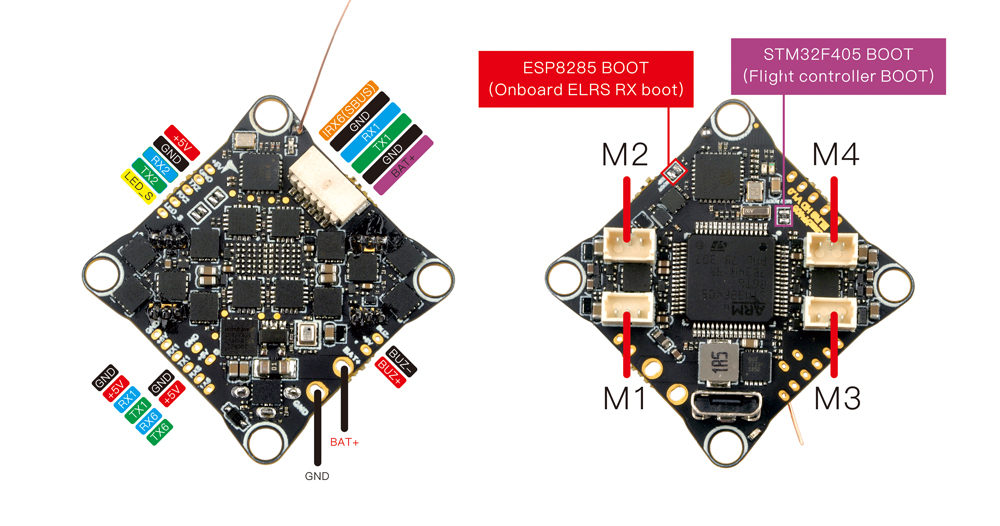
UART Mapping
The UARTs are marked Rn and Tn in the above pinouts. The Rn pin is the receive pin for UARTn. The Tn pin is the transmit pin for UARTn.
SERIAL0 -> USB
SERIAL1 -> UART1 (DisplayPort, DMA-enabled)
SERIAL2 -> UART2 (RCin, connected to internal ELRS,DMA-enabled)
SERIAL5 -> UART6 (USER, DMA-enabled)
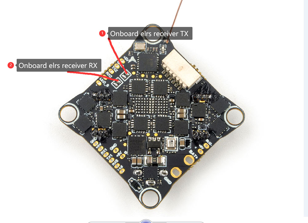
RC Input
RC input is configured on the on-board ELRS on UART2 or through (UART2_RX/UART2_TX) pins. It supports all serial RC protocols.
To disable the onboard ELRS module and use an external RC on TX2/RX2, desolder the RX/TX pads of the onboard ELRS receiver as shown in the image below:
OSD Support
The CrazyF405 is configured for Digital HD FPV using the HD VTX connector.
PWM Output
The Carzyf405HD AIO has 4 PWM outputs internally connected to its 4-in-1 ESC. The pads for motor output M1 to M4 are also on the board. All 4 outputs support DShot, as well as all PWM types. The default configuration is for DShot using the already installed BlueJay firmware.
Battery Monitoring
The board has a built-in voltage and a current sensor inputs tied to its 4 in 1 ESC current sensor. The voltage sensor can handle up to 2S LiPo/Li-Hv batteries.
The correct battery setting parameters are:
BATT_MONITOR = 4
BATT_VOLT_PIN = 12
BATT_VOLT_MULT = 10.9
BATT_CURR_PIN = 13
BATT_AMP_PERVLT = 50
These are set by default in the firmware and shouldn’t need to be adjusted
Compass
The BETAFPV F405 AIO does not have a builtin compass.
Firmware
Firmware for this board can be found here in sub-folders labeled “CrazyF405”.
Loading Firmware
Initial firmware load can be done with DFU by plugging in USB with the bootloader button pressed. Then you should load the “with_bl.hex” firmware, using your favourite DFU loading tool.
Once the initial firmware is loaded you can update the firmware using any ArduPilot ground station software. Updates should be done with the *.apj firmware files.