Electronic Fuel Injectors
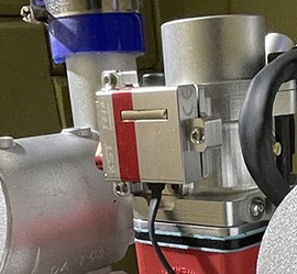
Photo courtesy of Lutan Engineering
ArduPilot provides support for several types of electronic fuel injection controllers for internal combustion engines. Both CAN and Serial communication interfaces to the EFI are supported.
Most units provide status information on RPM, Fuel flow, consumption, temperature, etc.
This information is reported in the autopilot logs via the EFI, EFI2, and ECYL log messages. Real time data is sent in the EFI MAVLink messages for monitoring by the GCS.
The following units have been tested and are supported:
NWPMU CAN bus
DroneCAN (adapted versions of the above serial units)
PiccoloCAN (Currawong’s ECU and IntelliJect EFI)
Using LUA script drivers:
Serial Setup
For the example below, the unit will assumed to be attached to SERIAL5 of the autopilot.
EFI_TYPE: MegaSquirt = 1, Lutan = 3, Hirth = 8
SERIAL5_PROTOCOL = 24 (Serial EFI))
SERIAL5_BAUD = 115 (115.2Kbaud)
Note
only one serial EFI is allowed in a given system
NWPMU Setup
For the example below, the unit will be assumed to be attached to the first CAN port.
EFI_TYPE = 2 (NWPMU)
CAN_P1_DRIVER = 1 (first driver)
CAN_D1_PROTOCOL = 6 (EFI_NWPMU)
DroneCAN Setup
For the example below, the unit will be assumed to be attached to the first CAN port.
EFI_TYPE = 5 (DroneCAN)
CAN_P1_DRIVER = 1 (first driver)
CAN_D1_PROTOCOL = 1 (DroneCAN)
PiccoloCAN Setup
For the example below, the unit will be assumed to be attached to the first CAN port.
EFI_TYPE = 6 (Currawong-ECU)
EFI_FUEL_DENS: Fuel density to calculate fuel consumption
CAN_P1_DRIVER = 1 (first driver)
CAN_D1_PROTOCOL = 4 (PiccoloCAN)
CAN_D1_PC_ECU_ID: Node ID to send throttle commands (Set to 0 to only receive telemetry)
MAVLink Setup
Some EFIs connect to the autopilot via MAVLink, instead of by a Serial port or DroneCAN. The following parameter should be set to connect such an EFI via MAVLink:
EFI_TYPE = 9 (MAV)
Note
the MAVLink library does not differentiate between different EFIs connected to the same MAVLink network
DLA Setup
Driver is provided via a LUA script. See LUA script setup instructions and the DLA EFI Lua md file for details.
Setup using LUA script drivers
Be sure your autopilot is capable of running LUA scripts. See List of Firmware Limitations by Board listing for your autopilot and be sure it does NOT list “SCRIPTING” under “Other” features as missing.
Setup LUA Scripting
Copy the appropriate driver script to your autopilot SD card from the LUA Driver directory
Follow the instructions in the driver’s “.md” file.
Using a Battery Monitor to Report Fuel Flow and Consumption
If an EFI is used in the system, either thru a LUA driver or the built-in drivers above, the fuel flow and consumption can be monitored using BATT_MONITOR = 27. The fuel flow in liters/hour will be reported as amps, while the fuel consumed in milliliters will be reported as mah.
Note
the MAVLink command to reset the fuel consumed does not work with this monitor.
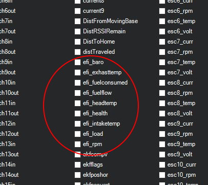
Displaying EFI telemetry in Mission Planner
The following EFI telemetry is available in the Mission Planner. Just right click in the DATA screens HUD display and select User Items. Then select what data to display.
Using the EFI RPM in ArduPilot
The EFI’s rpm telemetry can be used as the autopilot’s RPM sensor, for display in the GCS as above, or for use with the harmonic notch filter.
First, set either RPM1 or RPM2 sensor as being sourced from the EFI (examples will use RPM1):
set RPM1_TYPE = 3 (EFI)
then setup the RPM Sensor Based Dynamic Notch Setup
Throttle Linearization
Some serial EFIs use the ArduPilot throttle output PWM value to control the throttle instead of a servo. Often the engine thrust is not a linear relation to this value. ArduPilot provides up to a third order polynomial curve fit for PWM versus control value sent to the EFI by changing the following parameters from their default values (which is a linear fit):
EFI_THRLIN_EN = 1 to enable, then refresh parameters or reboot to show:
EFI_THRLIN_COEF1 First order polynomial fit term
EFI_THRLIN_COEF2 Second order polynomial fit term
EFI_THRLIN_COEF3 Third order polynomial fit term
EFI_THRLIN_OFS Offset term
throttle values are modified as:
ArduPilot scaled throttle output value = thr
modified throttle = (EFI_THRLIN_COEF3 * thr^3 + EFI_THRLIN_COEF2 * thr^2 + EFI_THRLIN_COEF1 * thr) + EFI_THRLIN_OFS
This allows the non-linearity to be compensated. The values for these parameters should be obtained from the EFI manufacturer, if applicable.