Using an Airspeed Sensor
Plane supports the use of an airspeed sensor, which can help in windy conditions, slow flight and autonomous landings. It is not recommended for most new users, however, as it does require additional tuning and adds one more layer of control to set up.
The following sections explain how to wire sensors to the autopilot and set them up. After you install an airspeed sensor don’t forget to calibrate it!
ARSPD_USE
ARSPD_USE enables airspeed use for automatic throttle modes instead of TRIM_THROTTLE as the target throttle setting (altered by TECS (Total Energy Control System) for Speed and Height Tuning Guide as needed during altitude control) . The autopilot continues to display and log airspeed if set to 0, but only airspeed sensor readings are used for control if set to 1. It will only use airspeed sensor readings for control when throttle is idle, if set to 2 (useful for gliders with airspeed sensors behind propellers).
If an airspeed sensor is used, the throttle stick will set the target airspeed in CRUISE and FBWB, while maintaining altitude target. In AUTO and GUIDED, it will use the AIRSPEED_CRUISE value unless THROTTLE_NUDGE is enabled and throttle stick is used to alter it, or a MAVLink command to change speed is sent to the vehicle.
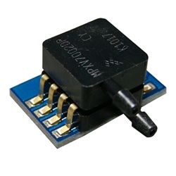
Airspeed Sensor Type
Airspeed sensors can be either analog or digital. The analog sensors connect to an A/D converter input pin on the autopilot, while digital sensors connect to the autopilot’s external I2C bus using the SDA and SCL external digital I/O pins or via DroneCAN. The type is set by the ARSPD_TYPE parameter. Analog sensors are type 2, DroneCAN sensors as type 8, and supported I2C bus digital sensors by other numbers.
If there is no sensor, be sure to set the ARSPD_TYPE to 0. ArduPilot calculates an sensor-less airspeed estimate that is used if no sensor is present or fails. ARSPD_TYPE must be set to zero in order to display this value if no sensor is present.
Warning
Many airspeed sensors are sensitive to light. Unless you are certain that the particular sensor used is not light sensitive, in order to avoid measurement errors, the sensor should be shielded from light.
Autopilot Airspeed Connection
A list of digital and DroneCAN airspeed sensors are listed below.
I2C
Connect the airspeed sensor to autopilots’s I2C port (or I2C splitter module). The ARSPD_BUS parameter must be set for the bus used to connect the sensor. Normally this defaults to “1” , and corresponds to the I2C bus normally designated for connecting the sensor. But if it is attached to another I2C bus (eg. compass, or on some autopilots its been mistakenly assigned) it will need to be changed to “0”. If the sensor fails to initialize (a GCS message will be sent if this is the case), then try changing the bus number and rebooting.
To enable the digital airspeed sensor, connect the autopilot to Mission Planner (or APM Planner for OS X), and select the Optional Hardware/Airspeed tab under the CONFIG menu. Using the drop-down box for Type, select your sensor’s type. The Pin dropdown is not used and can be ignored. Check the “Use Airpeed” box to use it in control, or leave it unchecked during in-flight calibration discussed below to check its operation before use.
DroneCAN
Attach the sensor to the AutoPilot’s DroneCAN port and select DroneCAN in the above mentioned Type dropdown box and check the “Use Airspeed” box as appropriate.
Analog Airspeed sensor
Analog sensors are now largely discontinued. Digital sensors are much more accurate and consistent over temperature. ArduPilot still supports these analog sensors, but they are not preferred. See Analog Airspeed Sensors.
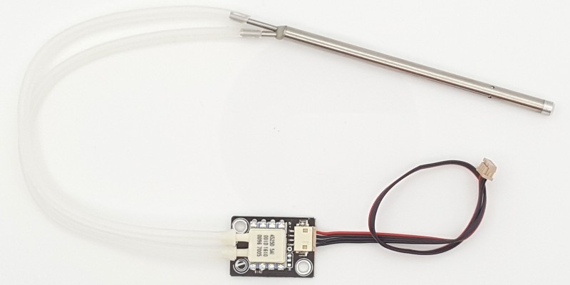
Installing the Pitot Tubes
When you place the airspeed sensor in your aircraft, use the pitot tube set in the kit (the kit comes with a single tube to measure both static and total pressure). In the case of the EasyStar, you’ll need to push it through the foam in the cockpit so it points straight into the airstream (drill or cut a small hole in the foam first). Make sure the holes in the side of the tube are not covered. They should be at least 1 centimeter out past the nose. First connect the two tubes coming out the back to the airspeed sensor. The tube coming straight out the back should go into the top port and the tube exiting at an angle should connect to the bottom port on the airspeed sensor.
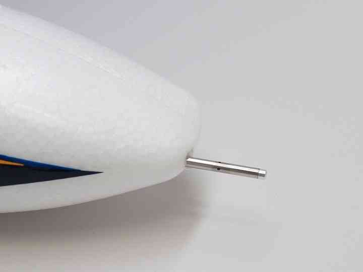
If you are using Plane in an aircraft with the propeller in the nose, the pitot tube must be mounted out on one wing, at least a foot from the fuselage to be outside the prop flow.
See Pitot Tube Considerations for more information on pitot tubes and placement considerations.
Checking operation
You can check the airspeed reading with Mission Planner or another ground station. Just blow on the pitot tube or press your finger over it and observe the response. In still air oscillation between zero and small values (2-3) is normal. The airspeed varies with the square root of the pressure, so for differential pressures near zero it varies quite a bit with very small pressure changes, while at flying speeds it takes much greater pressure changes to produce a similar change in speed. If you see mostly 0, 1, 2, with an occasional bounce to 3 or 4, consider it normal. You will not see that sort of variability at flying speeds.
Calibration
The airspeed sensor reading is automatically zeroed by the autopilot during initialization and value set in the ARSPD_OFFSET automatically, so it is good practice during windy conditions to placea loose fitting cover over the pitot tube that shields the front hole and the four small side holes from the wind. This cover should be fitted prior to power on and removed before flight. If you forget to do this, you can always place the cover and repeat the airspeed auto-zero using the Mission Planner’s PREFLIGHT CALIBRATE => Do Action.
Note
the DLVR type airspeed sensors do not require calibration at initialization and allow ARSPD_SKIP_CAL to be set to “1”, avoiding the need to cover the pitot during initialization.
The airspeed reading scale factor is adjusted using the ARSPD_RATIO parameter. Plane has an automatic calibration function that will adjust the value of ARSPD_RATIO automatically provided the plane is flown with frequent direction changes. A normal model flying field circuit pattern or loiter will achieve the required direction changes, cross-country flying will not. To enable automatic airspeed sensor calibration, set the value of ARSPD_AUTOCAL to 1. See Calibrating an Airspeed Sensor for more details.
Miscalibration Safeguards
In order to help prevent Airspeed sensor use when its been miss-calibrated either during ground static calibration during the power up sequence, or by accidental parameter changes to offset or ratio, three parameters are available. If the ground speed is consistently lower than the reported airspeed for a few seconds by ARSPD_WIND_MAX, i.e. the apparent wind speed is greater than that amount, the sensor can be disabled to avoid erroneous reporting. It can be allowed to re-enable if the apparent wind falls back below that value. These actions are controlled by ARSPD_OPTIONS.
You can also elect to have a GCS text message sent after the ground static calibration which reports the value of the calibration (ARSPD_OFFSET). This value should not change significantly (10-20 points) from power-up to power-up significantly. If it does, then you may have forgotten to cover the pitot during power up and need to recalibrate. This option can be selected in the ARSPD_OPTIONS bitmask parameter.
You can also send a warning to the Ground Control Station if the apparent wind exceeds ARSPD_WIND_WARN. This can be used instead of, or together with the above
Failure
A failing airspeed sensor can lead to the aircraft stalling or over-speeding, this is something that is hard for ArduPilot to detect. Likewise, accidentally miscalibrating the offset during ground initialization can occur if the pitot tube is not covered to prevent wind upsetting the calibration, and can result in wildly inaccurate readings. The parameters below can be used to help detect these conditions and warn of, and/or disable, a failed sensor.
ARSPD_WIND_MAX can be used to set the maximum expected wind speed the vehicle should ever see. This is then be used in combination with the GPS ground speed to detect a airspeed sensor error. ARSPD_WIND_WARN can be set to a lower speed to give some warning to the operator before the airspeed sensor is disabled. ARSPD_OPTIONS can be set to allow sensors to be disabled based on this wind speed metric, a second option bit allows then to be re-enabled if the speed error is resolved.
AHRS_WIND_MAX sets the maximum allowable airspeed and ground speed difference that will ever be used for navigation.
By default, these functions are disabled.
EKF3 affinity and lane switching is another option for dealing with airspeed sensor failure.
Balloon Drop
In the special case of a high altitude balloon drop, the EKF will declare the airspeed sensor faulty since there is gps speed but no airspeed due to air density. This can result in TECS miss-applying pitch. In this special case , the AHRS_OPTIONS bit 2 can be set to prevent EKF from declaring the airspeed sensor as faulty and continue to use it.
Airspeed sensors available from ArduPilot Partners:
I2C
- 4525DO
- ASP5033
- DLVR
DroneCAN
- 3DR ASUAV
- Amphenol AUAV (static and dynamic pressure)
- ASP5033
- MS4525