BotBlox DroneNet
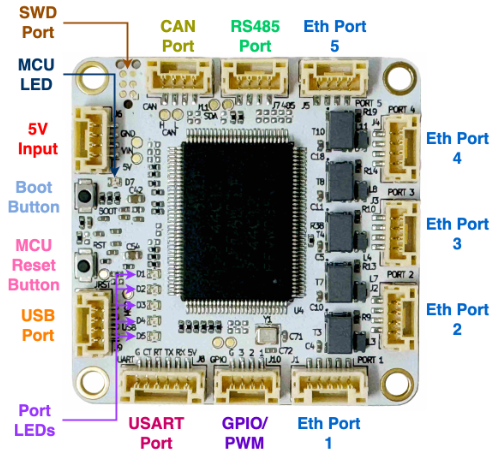
The BotBlox DroneNet ethernet adapter allows STM32 H7 autopilots without built-in ethernet support to connect to ethernet peripherals
Where To Buy
The BotBlox DroneNet can be purchased directly from BotBlox
Optionally the SwitchBlox Cable Adapter may be useful to ease the ethernet port differences across device manufacturers
Connecting to the Autopilot
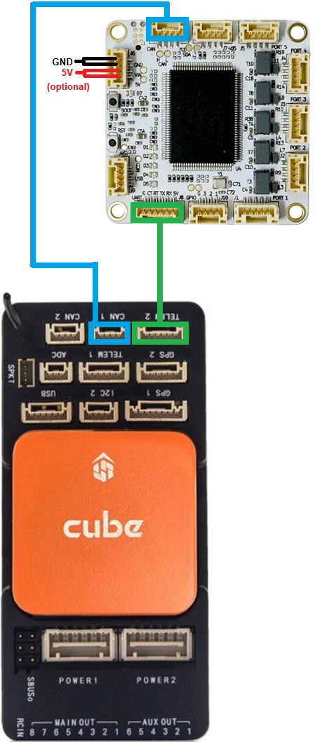
Connect one of the autopilot’s serial ports to the DroneNet’s UART port. For optimum performance the autopilot’s serial port should support flow control which normally means using Serial1 or Serial2. In the image above Serial2 is used.
Connect one of the autopilot’s CAN ports to the DroneNet’s CAN port. This connection is only used to configure the DroneNet device and so it maybe removed after the configuration is completed. In the image above the autopilot’s CAN1 is used.
5V Power can be provided through the dedicated power port or through the Serial or CAN port
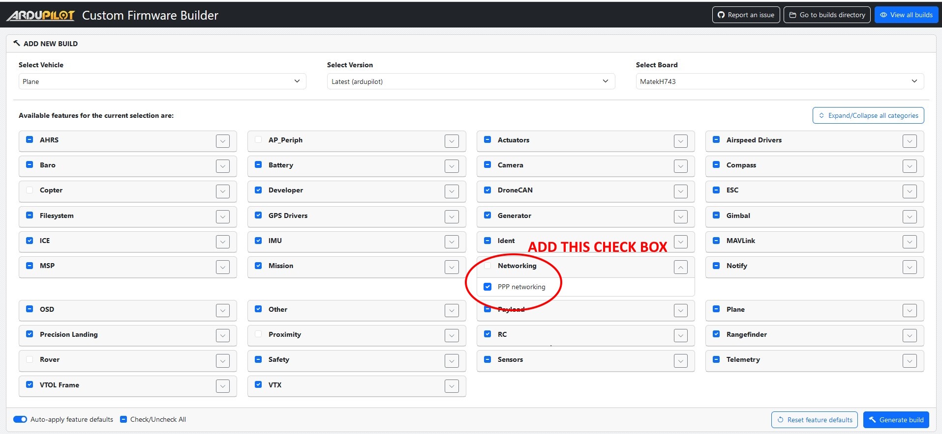
Install ArduPilot with PPP Support
PPP allows an autopilot to communicate over Ethernet using a serial port but with the exception of the CubePilot CubeOrangePlus, PPP is not included by default in the ArduPilot firmware.
Use the Custom Firmware Build Server to build a firmware that includes PPP support
Alternatively build the code yourself and enable PPP by adding
--enable-PPPto the waf configuration step
Autopilot Configuration
See the PPP configuration and ArduPilot Port Configuration sections of Ethernet / Network Setup but in short set these parameters:
CAN_P1_DRIVER = 1 (First driver)
CAN_D1_PROTOCOL = 1 (DroneCAN)
NET_ENABLE = 1
SERIAL2_PROTOCOL = 48 (PPP)
SERIAL2_BAUD = 12500000 (12.5MBaud)
To allow the autopilot to eventually communicate with other ethernet devices, the NET_P1_TYPE, NET_P1_PROTOCOL, etc parameters will need to be set. More details on the settings required can be found in the “Ethernet Connectivity” sections of the ArduPilot wiki page for the device. For example Siyi camera setups can be found on this page
DroneNet Setup
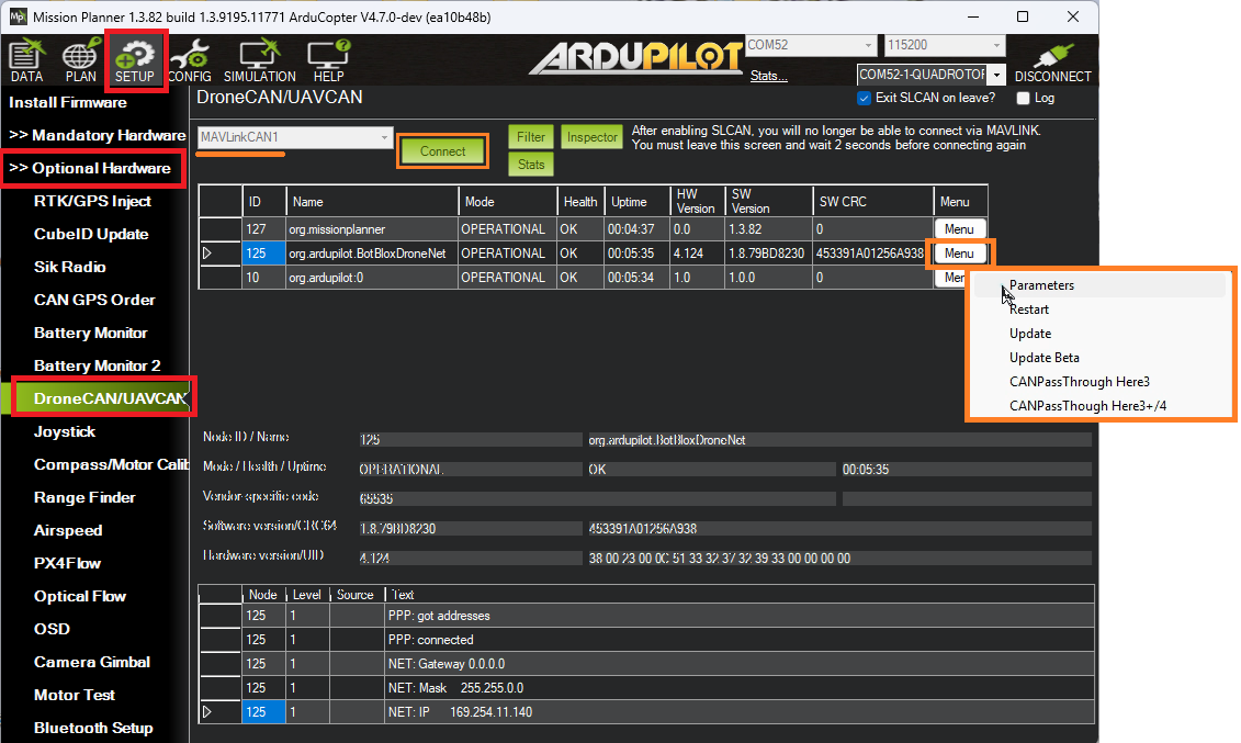
The DroneNet’s parameters can be set using Mission Planner’s DroneCAN screen or the DroneCAN GUI tool. The following instructions assume Mission Planner is used:
Connect to the AutoPilot with Mission Planner
Open the Setup, Optional Hardware, DroneCAN/UAVCAN screen
From the top-left drop-down select MAVLinkCAN1 (or MAVLinkCAN2 if the autopilot’s CAN2 is used)
Press “Connect” and the table should be populated with the available DroneCAN devices including “org.ardupilot.BotBloxDroneNet”
Press the “Menu” button on the right side and select “Parameters”
Set the following parameters and press the “Write” button
NET_DHCP = 0 (to disable dynamic IP assignment)
NET_IPADDR0 = 192 (default)
NET_IPADDR1 = 168 (default)
NET_IPADDR2 = 144
NET_IPADDR3 = 14
NET_GWADDR0 = 192 (default)
NET_GWADDR1 = 168 (default)
NET_GWADDR2 = 144
NET_GWADDR3 = 1
Reboot the system or from the DroneCAN screen select “Menu”, “Restart”
On the next autopilot reboot, messages like those shown below should appear. Note that the autopilot’s IP address’s final octet is one higher (e.g. “15”) than the DroneNet’s IP address (e.g. “14”)
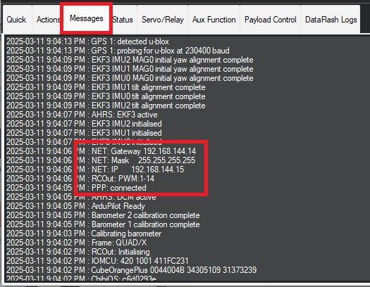
The IP addresses chosen above are somewhat arbitrary but work well for many systems. In general all ethernet devices on the drone should be in the same subnet meaning the first three octets of the IP address (e.g. 192.168.144.x) should match while the last octet should be unique to each device.
DroneNet WebServer
The DroneNet device has a built-in web server that can be used to update the firmware on the device

Connect a PC to the DroneNet’s ethernet
Set the PC’s IP address to be in the same subnet as the DroneNet (e.g. 192.168.144.99)
Open a web browser and enter the DroneNet’s IP address as the URL (e.g. “192.168.144.14”)
See the video linked below for more details on how to use the webserver to update the DroneNet’s firmware