Currawong Velocity CAN ESCs
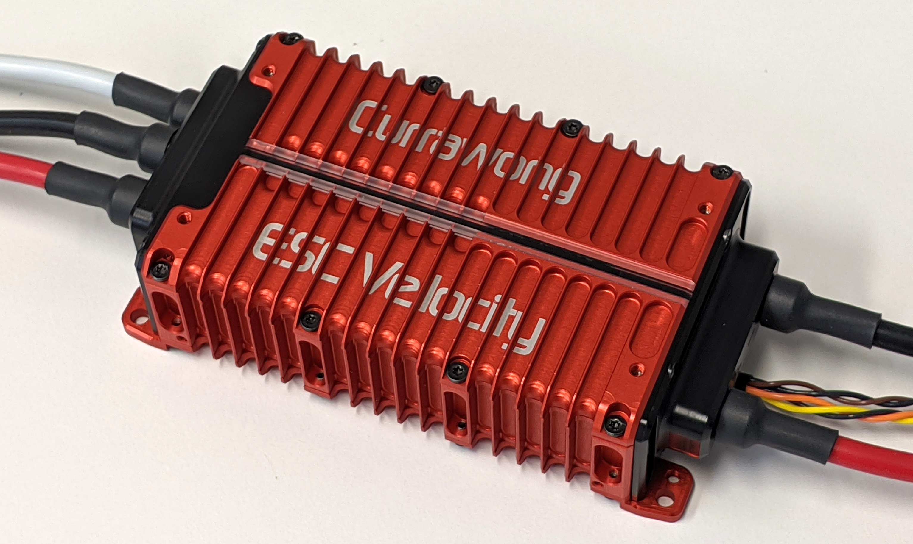
Currawong’s Velocity range of ESCs provide motor control for the aerospace sector, with a high degree of reliability.
Designed for driving extremely large motors for heavy-lift applications, the Velocity range of ESCs is available in power levels above 20kW
Up to 18S (75V) battery packs
Sustained currents above 300A
Compact design
Fully isolated communication interface
Designed and manufactured in Australia
The Velocity ESCs support both DroneCAN and PiccoloCAN for commands and telemetry. A traditional digital PWM interface is also supported.
Additionally, the Velocity ESC provides an optional hardware interlock for increased operator safety.
Where to Buy
Contact Currawong Engineering for purchasing details.
DroneCAN Setup
DroneCAN ESCs setup is described on the DroneCAN ESCs Autopilot Setup page but in short set the following parameters on the autopilot:
Set CAN_P1_DRIVER = 1 (First driver) to specify that the ESCs are connected to the CAN1 port
Set CAN_D1_PROTOCOL = 1 (DroneCAN)
Set
SERVOx_MIN= 1000 andSERVOx_MAX= 2000 for each ESC connected (xcorresponds to the ESC number) so ArduPilot uses an output range that matches the ESCs input rangeSet
SERVOx_FUNCTIONto each motor channel (e.g. 33 - 40 for motors 1 - 8). This is automatically configured when setting frame class/type. If a motor channel isn’t assigned to a servo output, commands won’t be sent to the associated ESC.
ESC Configuration
The ESCs can be configured using the DroneCAN GUI Tool or DroneCAN Web Tool.
To configure the ESC to receive commands from
SERVOxoutput, setdronecan.escIndextox - 1(e.g. forSERVO5, setescIndex= 4). Note that this is different to PiccoloCAN, where motor channels are assigned to node ids, rather than servo output channels to theescIndex.Telemetry periods can be configured with the
dronecan.messagePeriodssettings.By default, the ESC respects arming messages from the Autopilot. To always software enable the ESC when a command is received, and ignore arming messages, set
config.swInhibit= 1 (False).
By default, the Velocity ESC is configured to use Dynamic Node id Allocation (DNA). dronecan.nodeId should be set to “0” (to use DNA), unless all devices on the CAN bus are configured to use static IDs.
Only the DroneCAN specific settings are shown when fetching settings using the DroneCAN protocol. The full suite of Velocity ESC settings can be configured by enabling the show_advanced setting.
Note
It is recommended to configure your motor, and perform ESC and motor validation using PiccoloCAN with CEquip, and swap to DroneCAN, if required, during vehicle integration.
PiccoloCAN Setup
The Velocity ESC supports the PiccoloCAN protocol. Originally developed for the Piccolo autopilot, the protocol is now natively supported by ArduPilot.
Support for PiccoloCAN is available by default in ArduPilot 4.7 (and lower). If using ArduPilot 4.8 (and higher) please use the custom build server to create a firmware with the ‘AP_PICCOLOCAN_ENABLED’ build option enabled which can be done using the Custom Build Server
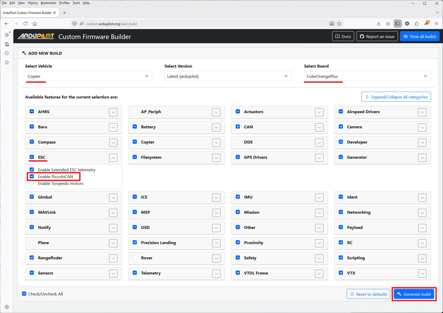
More instructions on using the Custom Build Server can be found here
ArduPilot Configuration
To enable communication with the Velocity ESCs using PiccoloCAN, the following parameters must be set.
Set CAN_P1_DRIVER = 1 (First driver) to specify that the ESCs are connected to the CAN1 port
Set CAN_D1_PROTOCOL = 4 (PiccoloCAN)
Set
SERVOx_MIN= 1000 andSERVOx_MAX= 2000 for each ESC connected (xcorresponds to the ESC number) so ArduPilot uses an output range that matches the ESCs input rangeSet
SERVOx_FUNCTIONto each motor channel (e.g. 33 - 40 for motors 1 - 8). This is automatically configured when setting frame class/type. If a motor channel isn’t assigned to a servo output, commands won’t be sent to the associated ESC.
By default, all configured motor channels are used to send control commands to Velocity ESCs. These control messages are transmitted by the autopilot at a default rate of 50Hz. These parameters can be modified using:
The CAN_D1_PC_ESC_BM parameter is a bitmask that determines which ESC (motor) channels are transmitted over CAN
The CAN_D1_PC_ESC_RT parameter determines the rate (Hz) at which commands are sent out to the connected Velocity ESCs
ESC Configuration
The following configuration settings should be used on the Velocity ESC for operation with Ardupilot:
Set Piccolo Node ID to the motor channel the ESC should listen to. Note this may not be the same as the configured servo output number.
Enable
Listen for Broadcast Commands.
Logging and Reporting
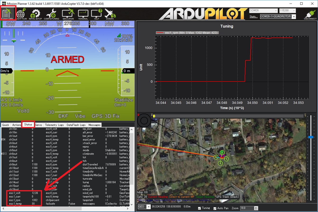
Velocity ESCs provide comprehensive telemetry information back to the autopilot which is recorded in the autopilot’s onboard log, and can be viewed in any ArduPilot compatible log viewer. This information includes:
RPM
Voltage
ESC Temperature
Motor current
Motor Temperature (when used with an external sensor)
This information (except the motor temperature) can also be viewed in real-time using a ground station. If using the Mission Planner go to the Flight Data screen’s status tab and look for (e.g.) esc1_rpm.
Note
Sending ESC data to the GCS requires using MAVLink2. Please check the appropriate SERIALx_PROTOCOL parameter is 2 (where “x” is the serial port number used for the telemetry connection).