MicoAir MTF-01 Optical Flow Sensor
The is a lightweight 2 in 1 optical flow sensor including a short range lidar which uses the serial MAVLink protocol to communicate with the autopilot. This can be used to improve horizontal position control especially in GPS denied or indoor environments.

Where to Buy
The sensor is available from Aliexpress and other resellers
Sensor Setup
Use MicoAir’s MicoAssistant software using an FTDI adapter (USB to serial) to set its output protocol to “mav-apm”.
Note
With firmware versions 4.5.0 or above, MTF-01 may not be recognized by ArduPilot unless you use MicoAssistant to modify its “mav_id” to 200 (any value other than 1) and disable MAVLink forwarding on the autopilot serial port it is connected to, as shown in the Parameters section below.
Connection to Autopilot
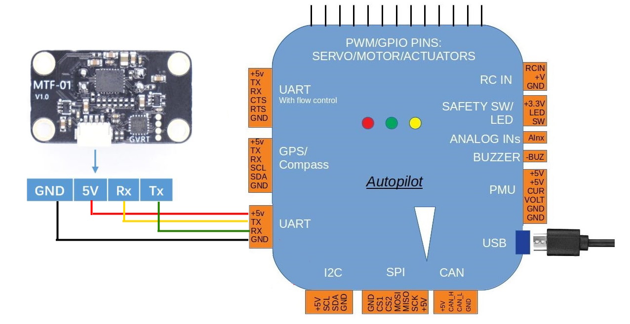
The flow sensor should be mounted on the underside of the copter with the camera lens pointing downwards.
Connect the sensor to the autopilots’ serial port
Mounting Orientation
MicoAir specifies a different default sensor orientation for ArduPilot/PX4 than for INAV/FMT: the orientation ArduPilot assumes with FLOW_ORIENT_YAW = 0 is rotated 180 degrees from the INAV/FMT one.
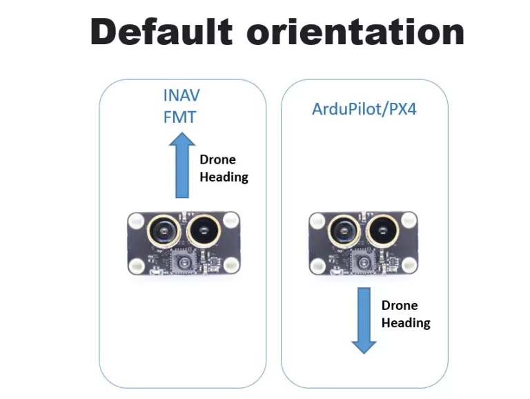
If the sensor is mounted in the INAV/FMT orientation instead, which is how many third party mounting diagrams show it, set FLOW_ORIENT_YAW = 18000 to rotate the sensor’s axes by 180 degrees to match.
Warning
An incorrect FLOW_ORIENT_YAW inverts the flow feedback, which produces a positive feedback loop and can lead to a flyaway. Always confirm the orientation using the flow versus attitude check described in Optical Flow setup before attempting a flight relying on optical flow.
Parameters
For the following we will assume it will be connected to Serial1 port of the autopilot. Any serial port can be used, however.
Set SERIAL1_BAUD = 115
Set SERIAL1_PROTOCOL = 1 (MAVLink1)
Reboot autopilot to see the MAVLink channel parameters for this port
Set
MAVx_OPTIONS= 2 (Don’t forward mavlink to/from) for the MAVLink channel used by this serial port.MAVxcounts the serial ports that use MAVLink, not theSERIALxnumber: if only SERIAL0 (USB) and SERIAL1 use MAVLink, SERIAL1 is MAV2_OPTIONS. See MAVLink Advanced Configuration.Set FLOW_TYPE = 5 (MAVLink)
Set RNGFND1_TYPE = 10 (MAVLink)
Reboot autopilot to see rangefinder parameters
Set RNGFND1_MAX = 8 to set range finder’s maximum range to 8m
Set RNGFND1_MIN = 0.01
Set RNGFND1_ORIENT = 25 (Downward)
Set SERIAL1_BAUD = 115
Set SERIAL1_PROTOCOL = 1 (MAVLink1)
Set
SERIAL1_OPTIONS= 1024 (bit 10, Don’t forward mavlink to/from)Set FLOW_TYPE = 5 (MAVLink)
Set RNGFND1_TYPE = 10 (MAVLink)
Reboot autopilot to see rangefinder parameters
Set RNGFND1_MAX = 8 to set range finder’s maximum range to 8m
Set RNGFND1_MIN = 0.01
Set RNGFND1_ORIENT = 25 (Downward)
Once the sensor is active you should be able to observe the optical flow and range sensor data on the Mission Planner’s “Status” page. The “opt_qua” and “rangefinder1” should have some value.
Optical Flow Use and Calibration
Be sure to follow the setup and calibration instructions and parameters for Optical Flow setup and how to switch between outdoor(GPS) and indoor (Optical Flow) positioning.