Analog Airspeed Sensors
Note
Analog airspeed sensors are becoming hard to obtain, since digital sensors are now as inexpensive and much more accurate and stable. Use of a digital airspeed sensor, versus an analog sensor is highly recommended.
The way this airspeed sensor works is that the top tube is “active” (measures air pressure from the pitot tube that is open at the front and has air driven into it by airspeed) and the bottom one is “static” (measures ambient air pressure from tube with intakes on the side).
Connect the active sensor port using silicon tube to the straight tube exiting from the rear of the pitot tube. The angled tube is the static part connecting to the static port of the sensor (the port on the sensor closest to the PCB)
Set the ARSPD_TYPE to 1.
PX4/Pixhawk Analog Airspeed Pin and Wiring
For the PX4
Hardware PIN 11 is available on the PX4 for airspeed use.
The “airspeed” pin 11 is located on a 3 pin DF13 connector on the PX4IO board but is directly connected to the ADC on the PX4FMU.
This pin can take voltages up to 6.6V (it has an internal voltage divider).
The FMU-Pres (air pressure) 3 pin connector is on the end of the PX4IO board opposite the power in connector.
Wire the airspeed sensor’s signal wire to pin 2 (the center pin) of the FMU-PRES connector.
Wire pin 1 (towards the center of the board) to the sensors VCC (5 volts) input.
Wire pin 3 (nearest the edge of the board) to the airspeed sensors ground.
Assign the airspeed sensor to an appropriate “PIN” in Mission Planner - Configuration - Advanced Params - Adv Parameter List.
Set the ARSPD_PIN parameter to 11 in the Advanced Parameter List and select “Write Parameters”.
For the Pixhawk
The “airspeed” pin 15 is located on a 3 pin DF13 connector on the Pixhawk board.
This pin can take voltages up to 6.6V (it has an internal voltage divider).
The air pressure connector (labeled ADC 6.6V) is a 3 pin connector on the top right of the Pixhawk.
Wire the airspeed sensor’s signal wire to pin 2 (the center pin) of the connector.
Wire pin 1 (towards the center of the board) to the sensor’s VCC (5 volts) input.
Wire pin 3 (nearest the edge of the board) to the airspeed sensor’s ground.
Assign the airspeed sensor to an appropriate “PIN” in Mission Planner - Configuration - Advanced Params - Adv Parameter List.
For other autopilots:
Many have an analog RSSI input pin that can serve as the analog airspeed sensor input.
Note
Most analog sensors output a signal from 0 to 5V, but most RSSI inputs are 3.3V maximum. If you will never exceed ~60% of the sensor’s maximum speed output (normally ~ 200mph for 5V), you will not exceed that rating. However, if you might or just want to be absolutely safe, you can use a 2:1 resistive voltage divider on the signal before applying to the autopilot RSSI input pin.
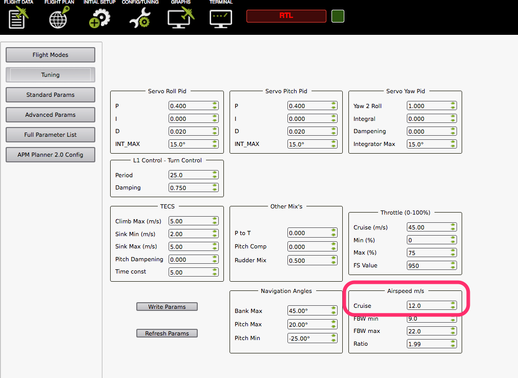
Once you have the airspeed sensor connected, you can use it to control aircraft speed in auto modes. Change the “Cruise” setting in the Tuning screen of either APM Planner (shown) or Mission Planner:
Using a different pin for the airspeed sensor
To assign the airspeed sensor to a specific pin, hook up your autopilot to your PC via USB. Start Mission Planner and select the Connect button on the upper right of the page.
Select the Configuration tab then Advanced Params and then the Adv Parameter List. Scroll down the list to the ARSPD_PIN parameter and select the pin you wish to use.
Set this to 0..9 for the APM2 analog pins.
Set to 64 on an APM1 for the dedicated airspeed port on the end of the board.
Set to 11 on PX4 for the analog airspeed port.
Set to 65 on the PX4 for an I2C airspeed sensor.
Set to the listed RSSI pin in other board’s documentation,often it is pin 0.
- After you have selected the pin, select the “Update Parameters” tab and
close Mission Planner.
Additional information on setting the airspeed sensor pin can be found here.