ROS and VIO tracking camera for non-GPS Navigation
This wiki page describes how a VIO tracking camera such as the Intel RealSense T265 can be used with ROS to facilitate non-GPS flight.
Note
Explanation for some parts of the system will be kept short for the sake of brevity. More in-depth discussion can be found in the following blog posts part 1, part 2, part 3.
Video
Hardware Requirements
Companion computer: Raspberry Pi 3 Model B
Note
Depends on what you need from the T265, the companion computer should have USB2 (pose data only) or USB3 (pose + image data). For localization and navigation, we only need to capture pose data, so RPi 3B is sufficient for the task.
System Overview
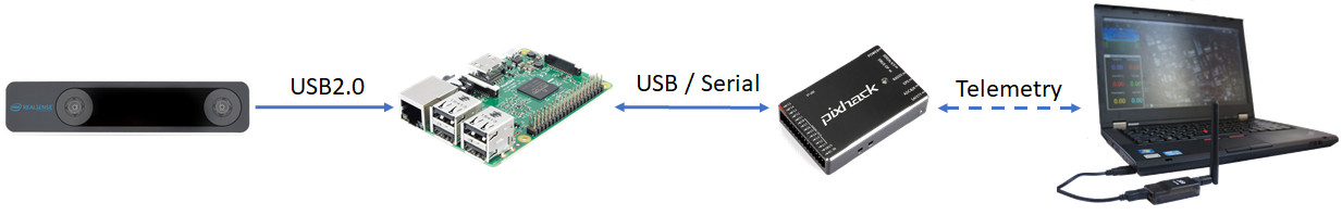
The position data obtained from realsense-ros node will be processed by vision_to_mavros node and send to mavros node via the topic /mavros/vision_pose/pose. mavros will take care of the ENU - NED frames transformation and send it to ArduPilot through MAVLink.
Install librealsense
Note
The Realsense T265 is supported via librealsense on Windows and Linux. Installation process varies widely for different systems. Refer to the official github page for instructions on specific system, such as Jetson, Odroid, Windows, Raspbian.
The following steps are intended for Ubuntu Linux. Since no Debian package is available for RPi, librealsense must be built from source.
Install OS (if you have not done so): Ubuntu MATE 16.04 LTS.
Increase swap size: RPi does not have enough RAM to compile the SDK, hence swap size needs to be increased. Swap size of 2048 (2GB) seems to work well, but you can go with less.
# Toggle swap off
sudo dphys-swapfile swapoff

# Edit the config file
sudo nano /etc/dphys-swapfile

# Find and edit the variable CONF_SWAPSIZE=2048

# Toggle swap back on
sudo dphys-swapfile swapon

# Reboot your raspberry
sudo reboot

# After reboot, check that swap size changed
free

# Should show something like Swap: 2097148
Clone librealsense repo and compile SDK
# Update system
sudo apt update
sudo apt upgrade -y

# Install dependencies
sudo apt install git libssl-dev libusb-1.0-0-dev pkg-config -y
sudo apt install cmake python3-dev raspberrypi-kernel-headers -y

# Clone the repository under directory of your choosing
cd ~
git clone https://github.com/IntelRealSense/librealsense.git
cd librealsense

# Install udev rules
sudo cp config/99-realsense-libusb.rules /etc/udev/rules.d/
sudo udevadm control --reload-rules && udevadm trigger

# Create the destination directory
mkdir build
cd build

# Remove extra files if this is not your first run
xarg sudo rm < install_manifest.txt
rm CMakeCache.txt
export CC=/usr/bin/gcc-6
export CXX=/usr/bin/g++-6
cmake -D CMAKE_BUILD_TYPE="Release"\
-D FORCE_LIBUVC=ON \
-D BUILD_PYTHON_BINDINGS=ON \
-D BUILD_EXAMPLES=ON ..
make -j4
sudo make install
sudo ldconfig

# Finally, reboot the pi:
sudo reboot
Test that librealsense is installed correctly: The easiest way is to plug in the T265 and play with the examples and tools included in the SDK.
If you have a monitor plugged in, you can open Intel Realsense Viewer by typing in into the terminal:
realsense-viewer. If the T265 is connected, the device will be available on the left panel. Click on the slider to start the device and switch to 3D view. Move the T265 around and you should see its trajectory.If no monitor is connected, other demos can also be launched from the terminal, for example
rs-pose,rs-pose-predict,rs-captureetc.
Test pyrealsense2 python wrapper: If you enabled building Python wrapper (
BUILD_PYTHON_BINDINGSflag), the compiled library is located in the build folder:~/librealsense/build/wrappers/python.Update the
PYTHONPATHenvironment variable to add the path to thepyrealsenselibrary:export PYTHONPATH=$PYTHONPATH:/usr/local/lib. Alternatively, copy the build output (librealsense2.soandpyrealsense2.sofiles, located in~/librealsense/build/) next to your script.The basic examples provided by Intel can be found in the folder
~/librealsense/wrappers/python/example. Run it with Python3.
export PYTHONPATH=$PYTHONPATH:/usr/local/lib

cd ~/librealsense/wrappers/python/example

# You should see a stream of data coming from the T265.
python3 t265_example.py
Note
The RPi 3B with USB2 cannot handle the image streams. Trying to display the fisheye images might crash the application.
Install realsense-ros
The installation steps for ROS are straightforward and you can follow the instruction on the official repo here.
Launch the node:
roslaunch realsense2_camera rs_t265.launch. All sensor data will be published as ROS topics:
/camera/odom/sample
/camera/accel/sample
/camera/gyro/sample
/camera/fisheye1/image_raw (not viewable on RPi 3B)
/camera/fisheye2/image_raw (not viewable on RPi 3B)
In another terminal, run
topto view current CPU usage.
Note
The version of realsense-ros needs to match with the version of librealsense, so every time you update ros/lib, the other should be updated as well.
Install mavros
Establish serial connection: Connect RPi to ArduPilot with MAVLink.
If the connection between RPi-ArduPilot is established via the UART serial port, also change the setting in /boot/config.txt.
Install
mavros: follow instructions on our wiki page.Establish connection in ROS: Connect to ArduPilot with MAVROS.
Install vision_to_mavros
Clone and build the package:
# Navigate to catkin workspace
cd ~/catkin_ws/src

# Clone and build the repo
git clone https://github.com/hoangthien94/vision_to_mavros.git
cd ..
catkin_make
source ~/.bashrc

# Add source command to .bashrc for future use
# echo "source ~/catkin_ws/devel/setup.bash" >> ~/.bashrc
Modify parameters according to your T265 camera’s orientation: The default parameters are set for a front-facing camera. In the launch file
t265_tf_to_mavros.launch, modify paramsroll_cam,pitch_cam,yaw_cam,gamma_worldfrom the list of values or with your own values corresponding to your setup.
Note
There is a known issue about inconsistent yaw angle for down facing orientation and some workarounds have been discussed. As of this writing, here is what seems to work: the camera needs to be slightly tilted (i.e. not completely flat out) when it starts streaming poses (launching realsense-ros or calling librealsense’s API to invoke pose data. Otherwise, the yaw angle of the world coordinates might be randomly initialized.
Configure ArduPilot
Connect to the flight controller with a ground station (i.e. Mission Planner) and check that the following parameters are set as shown below:
AHRS_EKF_TYPE = 2 (the default) to use EKF2 (as of this writing, EKF3 is not supported for handling external navigation data)
EK2_ENABLE = 1 (the default)
EK3_ENABLE = 0 (the default)
GPS_TYPE = 0 to disable the GPS
EK2_GPS_TYPE = 3 to disable the EKF’s use of the GPS
EK2_POSNE_M_NSE = 0.1
EK2_VELD_M_NSE = 0.1
EK2_VELNE_M_NSE = 0.1
COMPASS_ENABLE = 0, COMPASS_USE = 0, COMPASS_USE2 = 0, COMPASS_USE3 = 0 to disable the EKF’s use of the compass and instead rely on the heading from external navigation data.
After the parameters are modified, reboot the flight controller.
Verify that all ROS nodes are working
There are 3 ROS nodes running in this setup: realsense-ros, mavros and vision_to_mavros. Launch in 3 separated terminals on:
realsense-rosnode:roslaunch realsense2_camera rs_t265.launch.The topic
/camera/odom/sample/and/tfshould be published at 200Hz.
mavrosnode:roslaunch mavros apm.launch(withfcu_urland other parameters inapm.launchmodified to your setup).rostopic echo /mavros/stateshould show that FCU is connected.rostopic echo /mavros/vision_pose/poseis not published.
vision_to_mavrosnode:roslaunch vision_to_mavros t265_tf_to_mavros.launchrostopic echo /mavros/vision_pose/poseshould now show pose data from the T265.rostopic hz /mavros/vision_pose/poseshould show that the topic is being published at 30Hz.
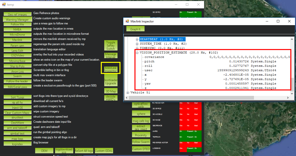
To verify that ArduPilot is receiving
VISION_POSITION_ESTIMATEon Mission Planner: pressCtrl+Fand click on “Mavlink Inspector”, you should be able to see data coming in.
Once all of the nodes can run successfully, next time you can launch all of them at once with
roslaunch vision_to_mavros t265_all_nodes.launch, which will launch:rs_t265.launch, as originally provided byrealsense-ros, no modification needed.apm.launch, modified with your own configuration.t265_tf_to_mavros.launchwith parameters according to your T265’s orientation.
Ground Test
After power on, launch all of the ROS nodes.
Generally (but not always), once
mavrosis running and the FCU starts receivingVISION_POSITION_ESTIMATEmessage, you will see the messages “GPS Glitch” and “GPS Glitch cleared” confirming that the external localization data is being recognized by the system.Now you need to tell the EKF where the vehicle is in the world (i.e. set EKF home), otherwise incoming data will not be fused. To do this, you need to send the MAVLink messages SET_GPS_GLOBAL_ORIGIN and SET_HOME_POSITION. There are a number of options for this to be done:
Use Mission Planner: Right-click on any point on the map >
Set Home Here>Set EKF Origin Here.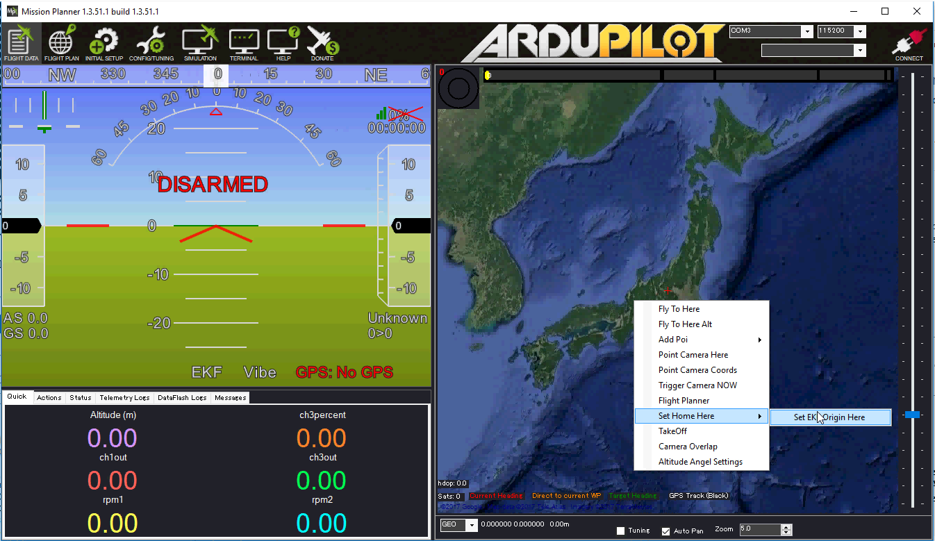
Use code: to send the required messages to the FCU through MAVLink. In Python, you can use this script set_origin.py.
Install
pymavlink: Follow the instructions here.Run the script:
rosrun vision_to_mavros set_origin.py.
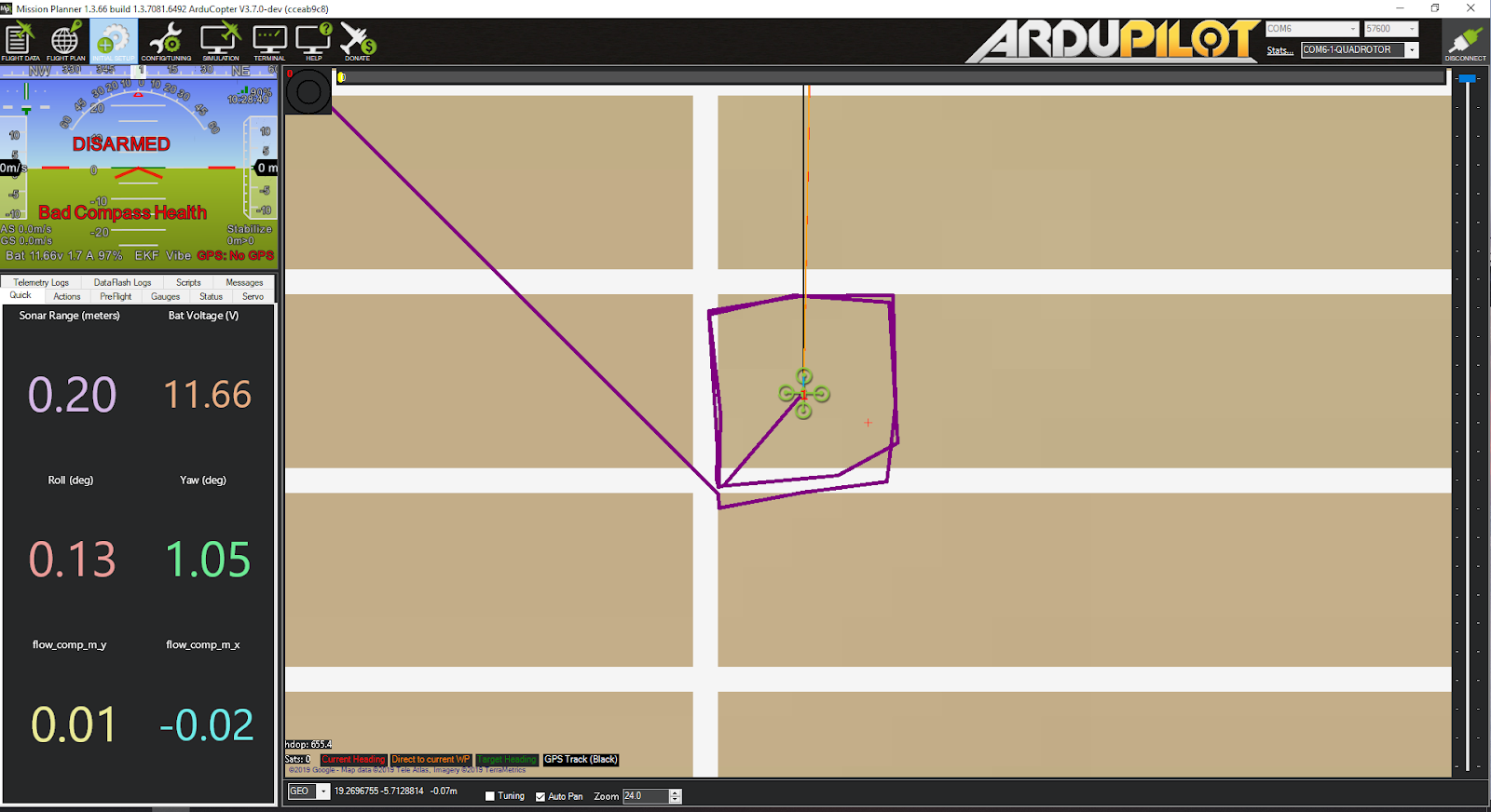
You should see a quadcopter icon appear on the map.
Pick-up the vehicle and walk it around, check that the vehicle’s position movements are shown on the map. The trajectory of the vehicle on the map should reflect the real movements without too much distortion or overshoot. Below is an example of walking in a 2m x 2m square.

Flight Test
For your first flight: - Takeoff in Stabilize or Alt-Hold, check that the vehicle is stable.
Move the vehicle around and observe the position on Mission Planner as well as
rvizto see if tracking is stable.Switch to Loiter, but always ready to switch back to Stabilize/Alt-Hold if anything goes awry.
Otherwise, the vehicle should hover stably and able to keep its position. Move the vehicle back and forth 2-3 meters, verify the scale (easier to view on
rviz).Move the vehicle around (translate, rotate) at varying speed, always ready to switch back to Stabilize/Alt-Hold.
If everything works as expected, next time you can arm and take-off in Loiter mode.
Tip
Always confirm that position feedback is running ok before switching to Loiter mode. Look out for the working boundary in your environment, i.e. where tracking might be lost due to lack of features, fast or rotation movement.
Data Logging
Visual odometry information will appear in the
VISOdataflash log messages.