Adding Simulated Peripherals to sim_vehicle
Several devices can be simulated within SITL. These include Gimbals, Beacons, Rangefinders, VICON, RPM sensors,etc.
Starting with CAN based simulated peripherals
When SITL is started, it has a standard set of peripherals (ie GPS, ESCs, Servos for flying surfaces, Power Monitors, etc.) simulated also. However, these can be simulated as DroneCAN devices instead to allow monitoring of CAN behavior, allow testing of new AP_Periph devices in the simulation, etc. To start SITL using these peripherals, instead of the normally connected ones:
sim_vehicle.py -v <vehicle> --console --map --can-peripherals
Simulating On-Board OSD
When starting SITL, you can have it display a simulation of the integrated OSD, if the autopilot includes one. Add the --osd option when starting SITL:
sim_vehicle.py -v ArduPlane --console --map --osd
Note
the OSD emulation displays OSD panel items and locations, but it does not allow multiple screens, nor units other than metric
Simulating I2C devices
Adding a Virtual Gimbal
SITL can simulate a virtual gimbal.
Note
Gimbal simulation causes SITL to start sending MOUNT_STATUS messages. These messages contain the orientation according to the last commands sent to the gimbal, not actual measured values. As a result, it is possible that the true gimbal position will not match - i.e. a command might be ignored or the gimbal might be moved manually. Changes are not visible in Mission Planner.
First start the simulator and use the following commands to set up the gimbal mount:
# Specify a servo-based mount:
param set MNT1_TYPE 1

# Set RC output 6 as pan servo:

param set SERVO6_FUNCTION 6


# Set RC output 8 as roll servo:
param set SERVO7_FUNCTION 8
Then stop and re-launch SITL with the -M flag:
sim_vehicle.py -M
Adding a Real Serial Gimbal
Adding a Rangefinder
SITL can simulate an analog rangefinder, which is very useful for developing flight modes that can use a rangefinder. To set it up use the following commands:
param set SIM_SONAR_SCALE 10
param set RNGFND1_TYPE 1
param set RNGFND1_SCALING 10
param set RNGFND1_PIN 0
param set RNGFND1_MAX 50
param set RNGFND1_MIN 0

# Enable rangefinder for landing (Plane only!)
param set RNGFND_LANDING 1
The above commands will set up an analog rangefinder with a maximum range of 50 meters (the 50m comes from an analog voltage range of 0 to 5V, and a scaling of 10). After making the above changes you need to restart SITL.
Then to test it try this:
module load graph
graph RANGEFINDER.distance
Then try a flight and see if the graph shows you the rangefinder distance.
Tip
You can also use the following commands to graph rangefinder information (defined as MAVProxy aliases):
grangealt- graph rangefinder distance and relative altitude.grangev- rangefinder voltagegrange- graph “rangefinder_roll”
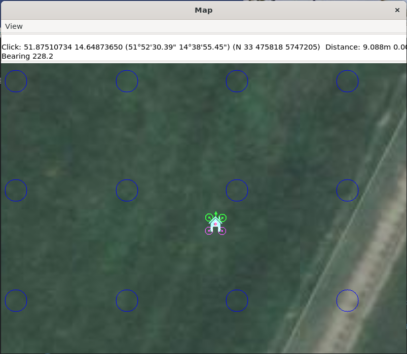
Adding a 360deg lidar
SITL can simulate a 360 deg lidar (LD06, RPLidarA2 or SF45b) which is useful for testing object avoidance. To set it up use the following commands:
param set SERIAL5_PROTOCOL 11 (Proximity)
param set PRX1_TYPE 16 (LD06)
  OR
param set PRX1_TYPE 5 (RPLidarA2)
  OR
param set PRX1_TYPE 8 (SF45b)
Next start the simulator using one of the lines shown below. This will start the vehicle in a location surrounded by virtual barriers
../Tools/autotest/sim_vehicle.py -A --serial5=sim:ld06 -l 51.8752066,14.6487840,54.15,0
../Tools/autotest/sim_vehicle.py -A --serial5=sim:rplidara2 -l 51.8752066,14.6487840,54.15,0
../Tools/autotest/sim_vehicle.py -A --serial5=sim:sf45b -l 51.8752066,14.6487840,54.15,0
To display the barriers on the map run type the following into the terminal
script /tmp/post-locations.scr
Adding an Optical Flow sensor
A virtual optical flow sensor can be added enabling a RangeFinder (see “Adding a Rangefinder” above) and then setting these parameters:
param set SIM_FLOW_ENABLE 1
param set FLOW_TYPE 10
Then restart SITL. After setting it up try this:
module load graph
graph OPTICAL_FLOW.flow_comp_m_x OPTICAL_FLOW.flow_comp_m_y
Go for a flight and see if you get reasonable data.
Adding an RPM sensor
Depending on the frame/vehicle you are simulating, its physics model might provide either the first or second RPM sensor, or both:
You can add an RPM sensor like this:
   param set RPM1_TYPE 10


or
param set RPM2_TYPE 10
the rpm sensor(s) can be associated with any motor output using the SIM_VIB_MOT_MASK parameter. For example, to associate an RPM sensor to the SITL plane model’s forward motor, which is default assigned to output 3, set the third bit in SIM_VIB_MOT_MASK parameter(value = 4).
The RPM can be displayed using:
graph RPM.rpm1 or RPM.rpm2
or
status RPM
Adding Wheel Encoders
You can test two virtual wheel encoders like this:
param set EK3_SRC1_POSXY 0
param set EK3_SRC1_VELXY 7
param set EK3_SRC1_VELZ 0
param set GPS_TYPE 0
param set WENC_TYPE 10
param fetch
param set WENC_POS_Y 0.075
param set WENC2_TYPE 10
param set WENC2_POS_Y -0.075
param set ARMING_SKIPCHK 8 (to disable GPS checks)
The restart SITL and right mouse button click on the map and select “Set Origin (with height)” and the vehicle should appear on the map. It may also be useful to enter “map set showsimpos 1” to make the vehicle’s actual position visible.
Adding Range Beacons
You can test a virtual range beacons by setting the following parameters
param set EK3_GPS_TYPE 3
param set GPS_TYPE 0
param set BCN_TYPE 10
param fetch
param set BCN_LATITUDE -35.363261
param set BCN_LONGITUDE 149.165230
param set BCN_ALT 584
The restart SITL and the vehicle should appear on the map. After perhaps 30seconds it should shift to its normal starting position.
Testing Precision Landing
Note
These instructions are written assuming ArduCopter
Enable Precision Landing, and set the precision landing backend type to SITL:
param set PLND_ENABLED 1
param fetch
param set PLND_TYPE 4
param set SIM_PLD_ENABLE 1
param set SIM_PLD_LAT -35.3632
param set SIM_PLD_LON 149.1652
A rangefinder is currently required for precision landing. Enable a simulated rangefinder:
param set RNGFND1_TYPE 1
param set RNGFND1_MIN_CM 0
param set RNGFND1_MAX_CM 4000
param set RNGFND1_PIN 0
param set RNGFND1_SCALING 12.12
Restart the simulation.
Takeoff and fly a bit, then switch into land:
arm throttle
rc 3 1800
mode land
rc 3 1500
Check the logs for precision landing messages:
ls -lt logs
Choose the youngest, then:
mavlogdump.py --type PL logs/<youngest>
Testing Vicon (aka Vision Positioning)
Start SITL, wiping parameters:
./Tools/autotest/sim_vehicle.py -v ArduCopter --gdb --debug -w
Enable EKF3, disable GPS and set Serial5 protocol to mavlink so as to accept vision-position-estimate and vision-speed-estimate messages:
param set EK3_SRC1_POSXY 6
param set EK3_SRC1_POSZ 6
param set EK3_SRC1_VELXY 6
param set EK3_SRC1_VELZ 6
param set EK3_SRC1_YAW 6
param set VISO_TYPE 2
param set SERIAL5_PROTOCOL 2
param set GPS_TYPE 0 (optional)
param set ARMING_SKIPCHK 8 (optional, to disable GPS checks)
param fetch
Restart the simulation, attaching a simulated Vicon system to SERIAL5:
../Tools/autotest/sim_vehicle.py --map --console -A "--serial5=sim:vicon:"
The console should indicate no GPS is present:
GPS: 0 (0)
Vision position estimates should now be being fed into ArduCopter:
STABILIZE> status VICON_POSITION_ESTIMATE
STABILIZE> 43371: VICON_POSITION_ESTIMATE {usec : 38380000, x : 0.0, y : 0.0, z : -0.0999755859375, roll : 0.0, pitch : 0.0, yaw : -0.122173137963}
You should also receive a startup message from the EKF:
APM: EKF3 IMU0 is using external nav data
APM: EKF3 IMU0 initial pos NED = 0.0,0.0,-0.1 (m)
APM: EKF3 IMU1 is using external nav data
APM: EKF3 IMU1 initial pos NED = 0.0,0.0,-0.1 (m)
Use MAVProxy’s right-click context menu item to Set Origin (with alt)
Arm in loiter, takeoff and fly somewhere:
loiter
arm throttle
rc 3 1800
rc 2 1400
Other SITL vicon settings are held in SIM_VICON_xx parameters:
param show SIM_VICON*
Simulating Multiple Flight Controllers on a Vehicle
The STANDBY Mode function (RCx_OPTION = 76) allows an autopilot to be put into a soft standby mode so that a second autopilot or companion computer can take control, but allow the first to resume later. In order to help in the code development of such systems, you can simulate two flight controllers operating in the simulation at the same time. The “master” instance, which has the active outputs into the sim is started declaring that there will be a “slave” instance which will be monitoring the sensors and running its code in parallel, but whose outputs are not connected into the simulation physics:
./Tools/autotest/sim_vehicle.py -v ArduCopter --slave 1
then another sim is started for the “slave” autopilot using:
./Tools/autotest/sim_vehicle.py -v ArduCopter -f json:0.0.0.0 -I1
you can then switch between whose outputs are being used by the simulation physics with the SIM_JSON_MASTER parameter ie O or 1.
The second simulation could be running code from a different branch on the same computer.
Adding a Slung Payload

A vehicle with a slung payload can be simulated by first following the setup instructions for real vehicles here which includes:
param set SCR_ENABLE 1
copy the copter-slung-payload.lua script to the “scripts” directory
copy the modules/MAVLink directory to the “scripts” directory
Then set up the simulated payload by doing the following:
param set SIM_SLUP_ENABLE 1
optionally set other simulated payload features:
SIM_SLUP_LINELEN: the length of the line between vehicle and payload (in meters)
SIM_SLUP_SYSID: system id of the payload
SIM_SLUP_WEIGHT: weight of the payload (in kg)
SIM_SLUP_DRAG: payload surface area drag. Higher values will cause the payload to be affected more by wind
optionally add simulated wind:
param set SIM_WIND_DIR 90 (to add wind blowing from east to west)
param set SIM_WIND_SPD 4 (to add 4m/s of wind)
Create an auto mission with SCRIPT_TIME and/or PAYLOAD_PLACE mission commands
Fly the mission in Auto mode and confirm the vehicle counteracts the movement of the slung payload during SCRIPT_TIME and/or PAYLOAD_PLACE mission commands
Adding a Winch
A virtual winch can be added to a copter by setting these parameters:
param set WINCH_TYPE 1
param set SERVO9_FUNCTION 88
param set RC9_OPTION 45
Then restart SITL. After setting it up try this:
module load graph
graph SERVO_OUTPUT_RAW.servo9_raw
rc 9 2000 (to release line)
rc 9 1000 (to wind in line)
rc 9 1500 (to stop winch from moving)
More instructions for controlling the winch using mavlink commands can be found on the MAVLink Interface Winch Control page