STorM32 Gimbal Controller
The STorM32-BGC is a relatively low-cost 3-axis brushless gimbal controller that can communicate with ArduPilot (Copter, Plane and Rover) using MAVLink or a proprietary serial protocol.
SToRM32 gimbals with I2C setups and firmware v0.96 should use the SToRM32 Serial driver
SToRM32 NT gimbals running firmware above v0.96 should use the SToRM32 MAVLink driver
Where to buy
Please refer to the STorM32-BGC wiki pages for more detailed information including where the gimbals can be purchased.
Warning
Some v1.3x boards has been found to cause significant RF interference on the 433mhz and 915mhz band. Use with caution, if you are using either 433/915mhz control or telemetry.
Note
Most available Storm32 gimbals do NOT have boards which support the latest MAVLink Gimbal Manage V2 protocols. Here is one that does.
Connecting the gimbal to the autopilot
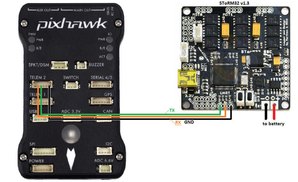
Connect one of the autopilot’s serial port’s TX, RX and GND pins to the gimbal’s UART port as shown above. The autopilot’s serial port’s VCC, RTS and CTS pins should not be connected
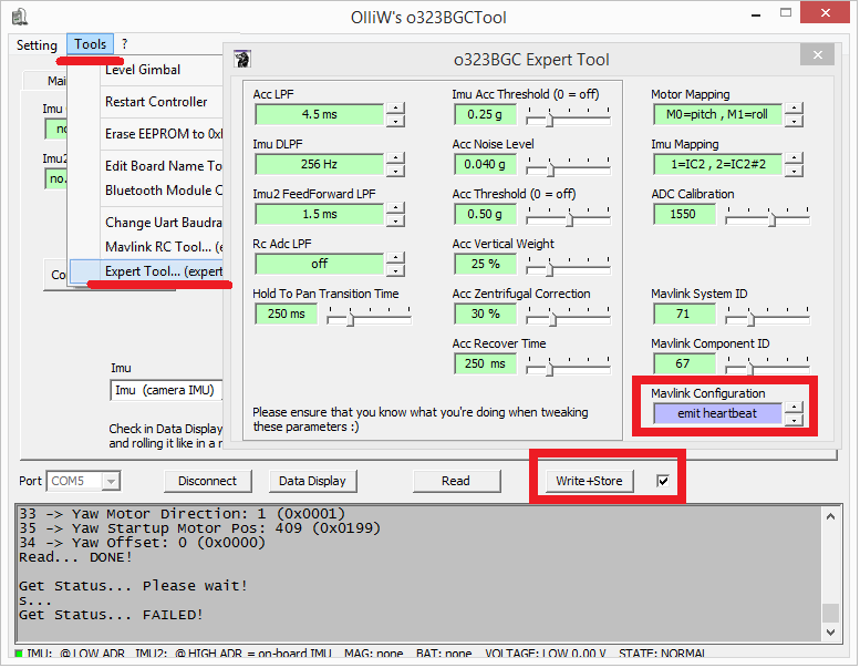
Setup if using MAVLink protocol
In addition to the regular gimbal configuration described on the STorM32-BGC wiki, the MAVlink heartbeats should be enabled through OlliW’s o323BGCTool’s Tools | Expert Tool screen as shown below.
Using a ground station (e.g. Mission Planner) set the following parameters. These setting assume Autopilot’s serial2 is being used. If another serial port is being used replace the “2” in the parameter name with the appropriate serial port number.
SERIAL2_BAUD = 115 (115200 bps).
SERIAL2_PROTOCOL = 1 (MAVLink1) or 2 (MAVLink2)
Optionally set BRD_SER2_RTSCTS = 0 to disable serial flow control

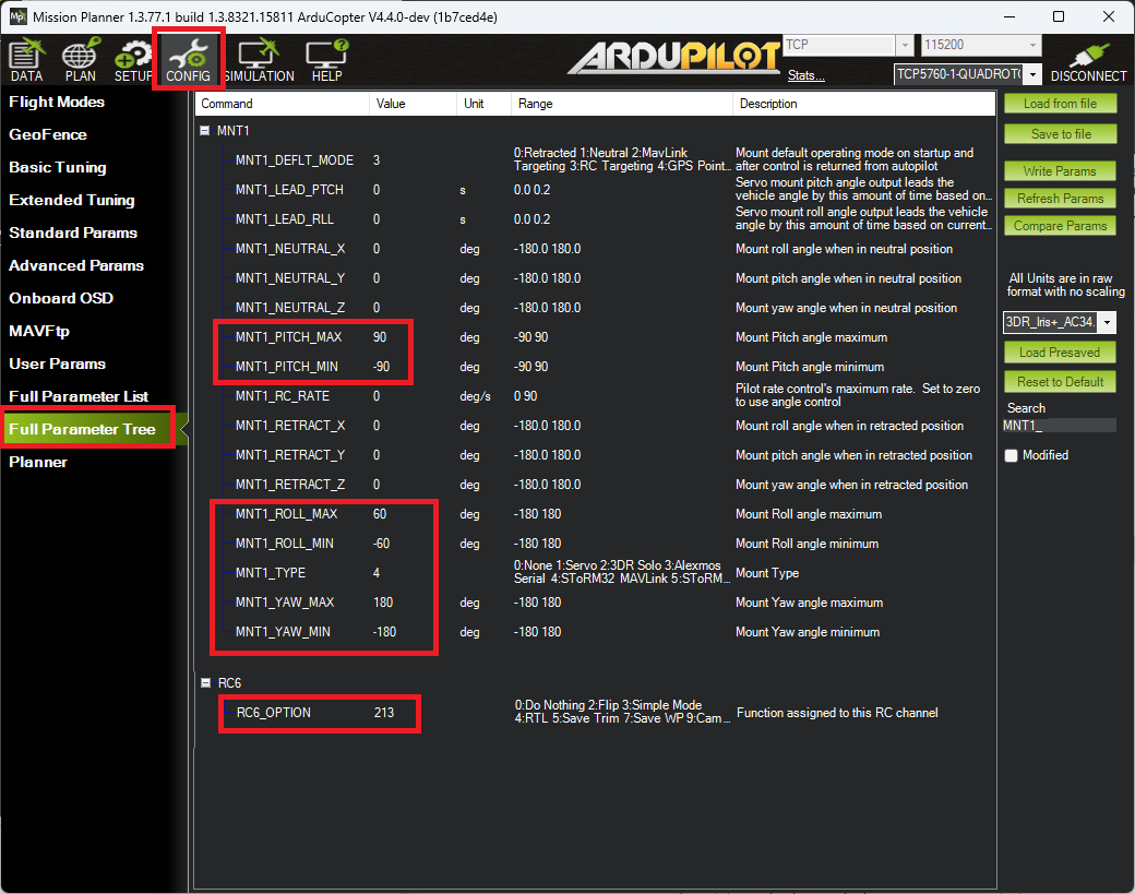
if the first mount is being used, set the following parameters:
MNT1_TYPE = 4 (SToRM32 MAVLink) and reboot the autopilot
set MNT1_YAW_MIN, MNT1_YAW_MAX, MNT1_PITCH_MIN, MNT1_PITCH_MAX, MNT1_ROLL_MIN, MNT1_ROLL_MAX to match your gimbal’s range.
Optionally set RC6_OPTION = 213 to control the gimbal’s pitch from the transmitter’s ch6 tuning knob.
The screenshot below shows a setup in which the gimbal has:
360 of yaw rotation (MNT1_YAW_MIN = -180, MNT1_YAW_MAX = 179)
60 degrees (both left and right) of roll (MNT1_ROLL_MIN = -60, MNT1_ROLL_MAX = +60)
Can point straight down (MNT1_PITCH_MIN = -9000)
Can point straight up (MNT1_PITCH_MAX = +90)
Gimbal’s pitch is controlled by the transmitter’s channel 6 tuning knob
Setup if using SToRM32 Serial protocol
To use the serial protocol use all the same settings as above except:
When Configuring the Gimbal controller set the “MAVLink configuration” parameter to “no heartbeat”
SERIAL2_PROTOCOL = 8 (SToRM32 Gimbal Serial). If another serial port is connected to the gimbal replace “2” with the serial port number
MNT1_TYPE = 5 (SToRM32 Serial)
Optional
To allow pilot RC transmitter control of the gimbal in RC targeting mode:
RC6_OPTION = 213 (“Mount Pitch”) to control the gimbal’s pitch angle with RC channel 6
RC7_OPTION = 214 (“Mount Yaw”) to control the gimbal’s yaw angle with RC channel 7
RC8_OPTION = 163 (“Mount Yaw Lock”) to switch between normal yaw operation and locking mount heading with RC channel 8 (in RC Targeting mode only).
RC9_OPTION = 185 (“Mount RP Lock”) to switch between three modes of earth frame/body frame locks for the roll and pitch axis in RC targeting mode.
Mount RP Lock Switch Position |
Roll EF/BF |
Pitch EF/BF |
Description |
|---|---|---|---|
LOW |
BF |
BF |
FPV lock: pitch/roll RC sets locked angle with respect to mount;useful when flying via gimbal camera |
MID |
BF |
EF |
Pitch lock: roll RC sets locked angle with respect to mount |
HIGH |
EF |
EF |
Horizon lock: pitch/roll RC sets locked angle with respect to horizon |
BF = Body frame, EF = Earth Frame
Note
for full FPV lock the yaw axis should not be forced to Earth frame by a Mount Yaw Lock switch. See Gimbal / Mount Controls for more information on mount modes, pilot/autopilot targeting controls, and axes locks.
setting MNT1_OPTIONS bit 2 (value +4) can be used to for force FPV lock as given in the above table without the need for RC switches when in RC Targeting Mount Mode.
Control and Testing
See Gimbal / Mount Controls for details on how to control the gimbal using RC, GCS or Auto mode mission commands
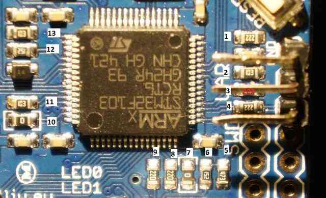
Resistor issue on some boards
Some in-depth analysis here on rcgroups turned up that some STorM32 boards need resistor #4 (shown in pic below) shorted (i.e. a wire soldered over the top of the resistor to turn it into a regular wire) in order for the gimbal controllers messages to get through to the Pixhawk.