Joystick/Gamepad
This article explains how you can control your vehicle with a Joystick or Gamepad using the Mission Planner which sends “RC Channel Override” messages to the vehicle.
Other GCSs including QGC also support “RC Channel Overrides” but they are not covered in this article.

Logitech F310 Joystick
Tip
Even if flying with a joystick, you should keep a regular transmitter/receiver connected and ready for use as a backup
What you will need
You will need the following equipment:
USB joystick or Gamepad such as the Logitech F310 (shown above).
A telemetry connection between your ground station and vehicle.
A laptop computer running Mission Planner.
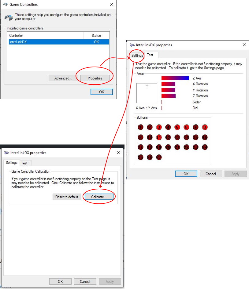
Calibration
First you must calibrate the joystick using the Windows joystick/game controller wizard.
Setup with the Mission Planner
Connect your USB joystick/gamepad to the PC
Open the Mission Planner Flight Data screen. On the Actions tab push the Joystick button
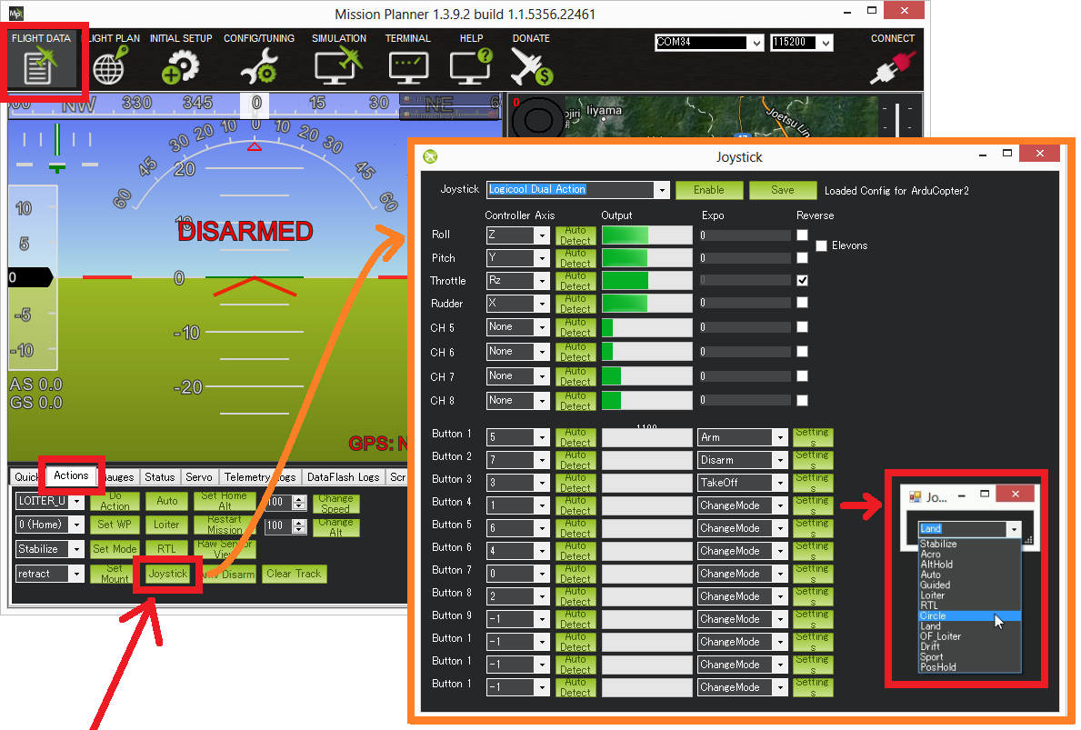
Ensure the joystick appears in the drop-down
The Enable button, once pushed, will tell the mission planner to start sending commands to the vehicle so for the initial setup do not push it.
On the “Roll” row, click the Auto Detect button and then waggle the control you wish to use for roll, left and right.
The channel can be reversed with the Reverse checkbox
The Expo number should be in the range of -100 to 100
0 = no expo
100 = low response around the middle, very fast response at the edges
-100 = very fast response around the middle, less response at the edges (very few people use negative expo)
Repeat for Pitch, Throttle and Rudder and push the Save button
You will likely want to set-up other buttons for Arm and Disarm
The flight mode channel (e.g. RC5 or RC8) and auxiliary function channels should not be controlled from the joystick especially if a regular RC receiver is also connected. Instead it is better to configure buttons to set the flight mode by selecting Change Mode and then push the Settings button and select the flight mode from the drop-down (see pic above). Details on why this is important are documented in issue #32862.
When done, push the Save button. This records the min and max calibrations and records the neutral positions of the joystick for the trim value. Mission Planner will then scale the joystick signal to the RC channel’s
RCx_MIN/MAX/TRIMparameters in the autopilot when sending RC override commands by the Joystick.
Autopilot Setup
These parameters configure how the RC inputs are consumed by the autopilot:
MAV_GCS_SYSID should match the GCS’s mavlink system ID. By default Mission Planner and QGC use 255, APM Planner 2 is 252. This parameter limits which GCS can send override signals to the vehicle.
RC_OVERRIDE_TIME: Timeout in seconds after which RC overrides will no longer be used, and regular RC input will resume. Default is 3 seconds. 0 will disable RC overrides, -1 will never timeout, and continue using overrides until they are disabled. If no regular RC is present on the vehicle this essentially defines the RC failsafe timeout.
RC_OPTIONS bit 1 (value 2) allow ignoring RC overrides completely
RC Auxiliary Function 46 (RC Override Enable) allows an RC input to enable/disable RC overrides. This may be useful to allow the pilot to easily switch between using a regular RC transmitter and joystick
Note
If you get an error PreArm: RC not calibrated (following calibration) you will additionally need to manually change RC1_MIN to 1101 and RC1_MAX to 1901 (and then repeat for RC2_, RC3_ and RC4_ max/min parameters).
This error is caused because Mission Planner maps the Joystick exactly to the RC min and max range, but the pre-arm checks assume that if the values are not at least 1 PWM us off the default value, that calibration has not been done. If you have RC calibrated your transmitter/receiver system already, this will not be necessary. DO NOT RC CALIBRATE THE JOYSTICK, it is not the same control mechanism as is used for RC systems. It uses MAVLink override messages.
Testing the controls before flying
Before flying for the first time you should test that all features work well.
To check the above controls move in the correct direction:
Click the Enable button on the Joystick setup screen to enable sending messages to the vehicle
Connect your autopilot to the computer with a USB cable
Push the Mission Planner’s Connect button
Go to the Initial Setup | Mandatory Hardware | Radio Calibration screen and ensure the green bars all move in the correct direction. Remember the bars move in the same direction as the sticks except for Pitch which moves in the opposite direction.
If any controls are reversed, check the Reverse checkbox on the Joystick setup screen.
Next test you are able to arm, disarm and switch into the various flight modes (no need to connect the battery)
Testing the failsafes
All of these tests should be performed on the ground with the battery disconnected or at least with the propellers off the vehicle.
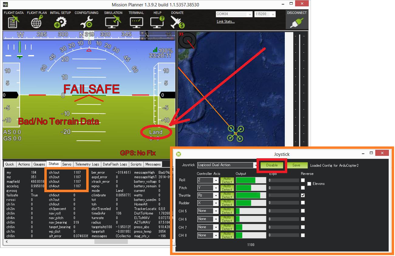
Simulate disabling the joystick in flight with transmitter off (i.e. no failover to regular transmitter):
Turn regular transmitter off
Connect with the mission planner, push Joystick window’s Enable button and ensure RC overrides are being sent to the vehicle. (use Radio Calibration screen or Flight Data’s status screen)
Arm vehicle, switch to Stabilize or Loiter mode and raise the throttle
Ensure the motors are spinning by checking the Flight Data screen’s “ch1out” ~ “ch4out”
Push Joystick screen’s Disable button
“Failsafe” should appear on the HUD and the vehicle should switch to “LAND” or “RTL”
Repeat the above test but at step #5 actually disconnect the joystick from the computer. The results should be the same.
Simulate failing over to the regular transmitter/receiver
Turn the regular transmitter on and ensure you can control the vehicle (perhaps by checking the Radio calibration page or the Flight Data screen’s Status tab’s “ch1in” ~ “ch8in”).
With the regular transmitter leave the vehicle in AltHold mode and raise the throttle to mid
On the Joystick screen push the Enable button
Arm the vehicle in STABILIZE mode and raise throttle to full (with the Joystick).
Check the throttle is at full in the Flight Data screen’s Status tab by checking “ch3in” is very high (around 1900 usually)
On the Joystick screen push the Disable button and check the “ch3in” has dropped to a mid value (around 1500)
The vehicle should remain in its current flight mode (Stabilize) but controls have been returned to the transmitter. The pilot’s inputs should be reflected in the “ch1in” ~ “ch8in” values. Switch the vehicle to AltHold mode by moving the flight mode switch.
Simulate loss of radio contact:
If radio contact is lost, the vehicle should respond as if the Joystick was “Disabled” or disconnected from the PC. You can test this by repeating the test above but instead of pushing the Disable button on the Joystick screen, disconnect the radio. In order to see the status of the vehicle you will need to connect two Mission Planner’s separately. The Mission Planner with the Joystick should be connected through telemetry and the 2nd Mission Planner should be connected through a USB connection.
Reducing lag in the controls
It is nearly impossible to make the Joystick as responsive as a regular transmitter but lag can be reduced by:
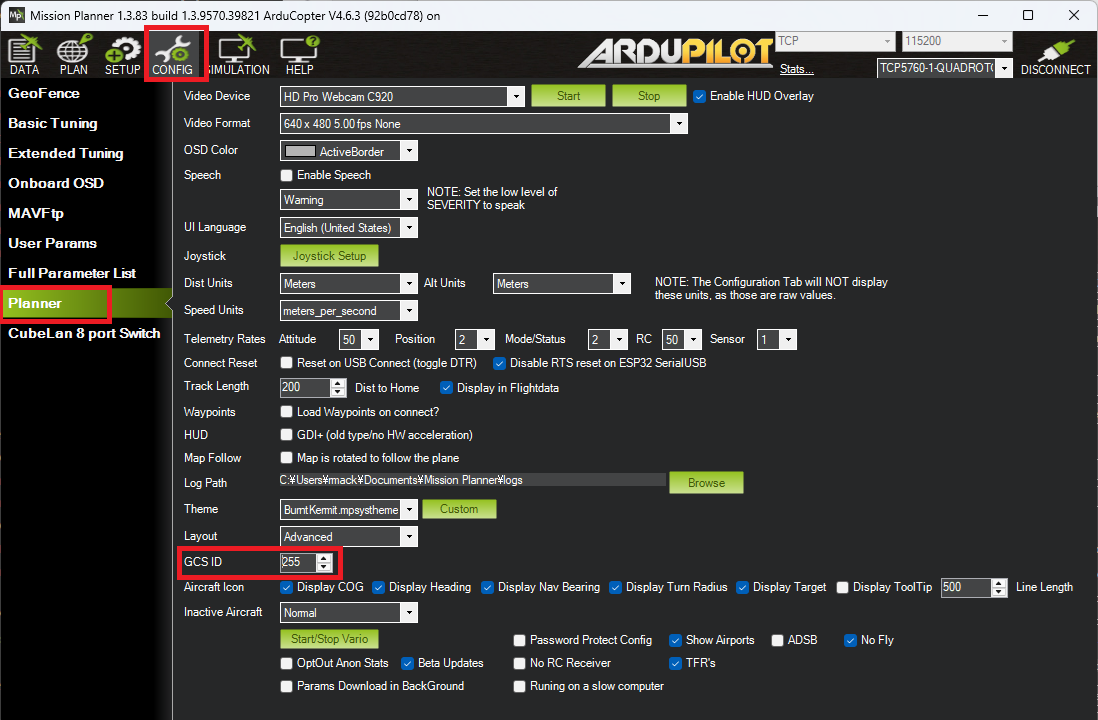
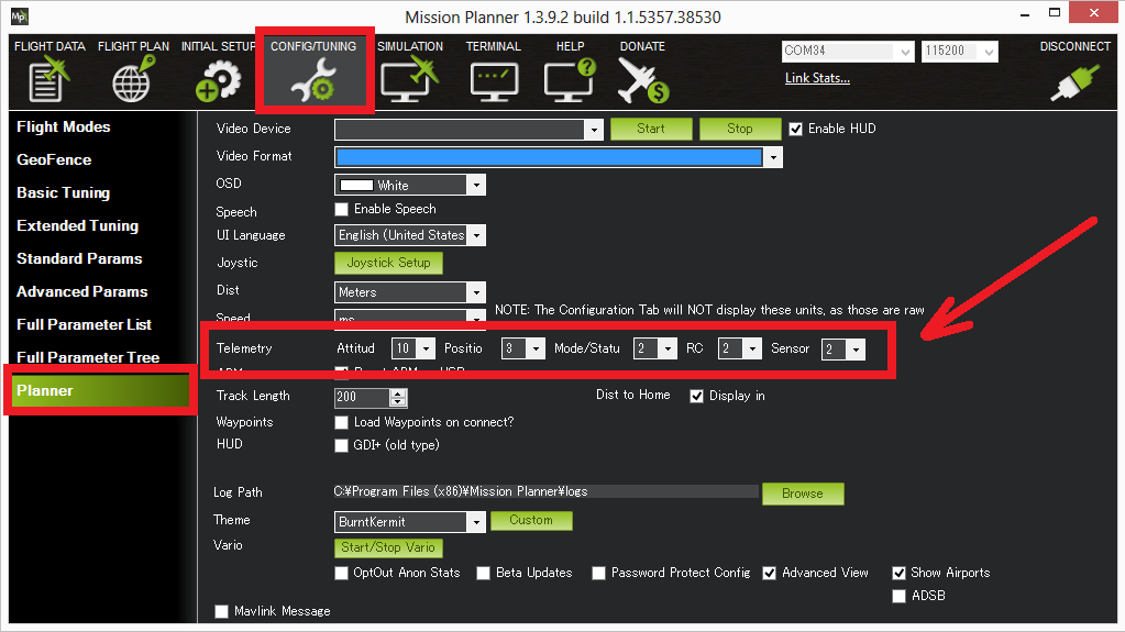
Reducing the rate of other telemetry data being sent between the vehicle and GCS from the MP’s Config/Tuning | Planner page
If using a SiK Radio or RFD900 Radio these can be put into Low Latency mode as described here.