Servo Gimbal
ArduPilot can stabilize a servo gimbal with up to three axis of motion using any of the free PWM output channels. Once connected the camera gimbal can be controlled by the pilot using an RC transmitter, by sending commands from the ground stations or autonomously during missions
Supported Gimbals
Any servo gimbal accepting PWM input should work. Specific examples include
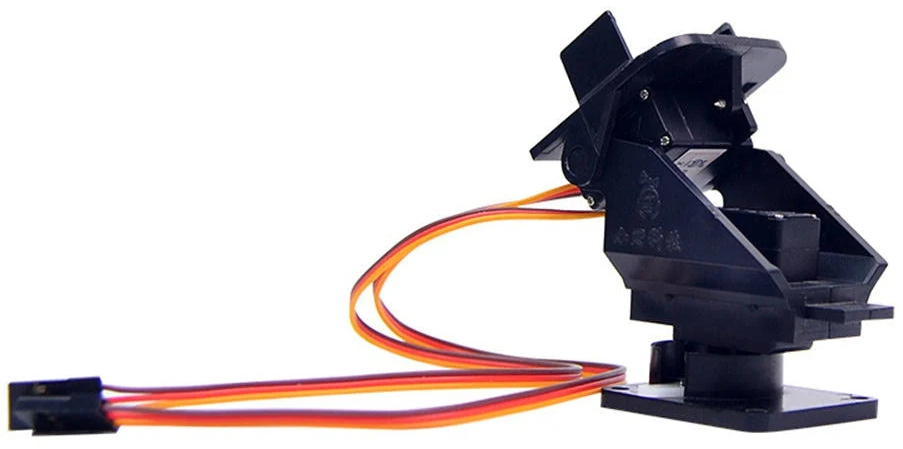
Adafruit Mini Pan-Tilt Kit
Mounting the Camera and Gimbal
The camera needs to be mounted securely to the gimbal, but in such a way that reduces/dampens vibrations from the motor.
Common methods for mounting the camera on the gimbal include using soft foam, stiff foam, neoprene tubes (mount camera on tube side), surgical tube, rubber bands, nylon bolts (direct stiff attachment) and velcro.
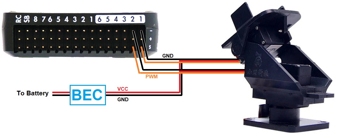
Connecting to the Autopilot
Connect the gimbal’s roll, pitch, and/or yaw servos signal and ground pins to the autopilot’s PWM output pins as shown below. Most autopilots do not provide power on the servo rail meaning a separate BEC is required.
Configuration
Note
Mission Planner includes a “Camera Gimbal” configuration screen but it has not yet been updated to work with ArduPilot 4.3 (and higher).
Connect to the autopilot with a ground station and set the following parameters. These settings assume the autopilot’s PWM outputs 9, 10 and 11 will control the gimbal’s roll, pitch and yaw angles respectively. They also assume common angular ranges of the gimbal which may need adjusting to match the actual gimbal being used.
Note
Currently up to two mounts can be supported, MNT1 and MNT2. The following parameters are for the first mount. The second mount has the same parameters.
MNT1_TYPE to 1 (Servo) and reboot the autopilot
MNT1_PITCH_MIN to -90 (meaning the gimbal can pitch straight downwards)
MNT1_PITCH_MAX to 25 (meaning the gimbal can pitch up by 25 deg)
MNT1_ROLL_MIN to -30 (meaning the gimbal can roll right 30 deg)
MNT1_ROLL_MAX to 30 (meaning the gimbal can roll left 30 deg)
MNT1_YAW_MIN to -180 (meaning the gimbal can yaw to the left 180deg)
MNT1_YAW_MAX to 180 (meaning the gimbal can yaw to the right 180deg)
MNT1_RC_RATE to 90 (deg/s) to control speed of gimbal when using RC targeting. If RC value is intended to control the ANGLE, then set it to 0.
Typical input and output assignments are shown below, but any unused RC input channel or autopilot output channels can be assigned for some or all of these functions.
SERVO9_FUNCTION to 8 (Mount1 Roll)
SERVO9_MIN and SERVO9_MAX to match the min and max range of the roll servo
SERVO10_FUNCTION to 7 (Mount1 Pitch)
SERVO11_MIN and SERVO11_MAX to match the min and max range of the yaw servo
Optional
RC6_OPTION = 213 (“Mount Pitch”) to control the gimbal’s pitch rate with RC channel 6
RC7_OPTION = 214 (“Mount Yaw”) to control the gimbal’s yaw rate with RC channel 7
RC8_OPTION = 163 (“Mount Yaw Lock”) to switch between normal yaw operation and locking mount heading with RC channel 8 (in RC Targeting mode only).
RC9_OPTION = 185 (Mount RP Lock) to roll and pitch axex locks as follows:
Mount RP Lock Switch Position |
Roll EF/BF |
Pitch EF/BF |
Description |
|---|---|---|---|
LOW |
BF |
BF |
FPV lock: pitch/roll RC sets locked angle with respect to mount;useful when flying via gimbal camera |
MID |
BF |
EF |
Pitch lock: roll RC sets locked angle with respect to mount |
HIGH |
EF |
EF |
Horizon lock: pitch/roll RC sets locked angle with respect to horizon |
BF = Body frame, EF = Earth Frame
Note
for full FPV lock the yaw axis should not be forced to Earth frame by a Mount Yaw Lock switch. See Gimbal / Mount Controls for more information on mount modes, pilot/autopilot targeting controls, and axes locks.
setting MNT1_OPTIONS bit 2 (value +4) can be used to for force FPV lock as given in the above table without the need for RC switches when in RC Targeting Mount Mode.
Control and Testing
See Gimbal / Mount Controls for details on how to control the gimbal using RC, GCS or Auto mode mission commands
Shutter configuration
See Camera Shutter Configuration in Mission Planner for information on how to integrate shutter triggering with ArduPilot.
See Cameras and Gimbals page for links to various triggering methods.
See Gimbal / Mount Controls for mount control and targeting information.
Other Parameters
Since servos in the gimbal may react slower to position/angle changes in the vehicle’s roll and pitch as the vehicle moves about a target, the camera shot may have some visible lag in it. This can be reduced by using these parameters to have the gimbal outputs move a bit ahead of the movements of the vehicle.