Autopilot Output Functions
All autopilot servo/motor outputs may be mapped to any output function supported by ArduPilot. This page describes how to configure these output channels and what each of the available functions that can be assigned to an output are.
ArduPilot supports up to 32 outputs. These may be via DroneCAN ESCs or directly from autopilot outputs, or a mixture of both.
Note
See the left sidebar menu for major output categories to navigate to desired functions on this page quickly.
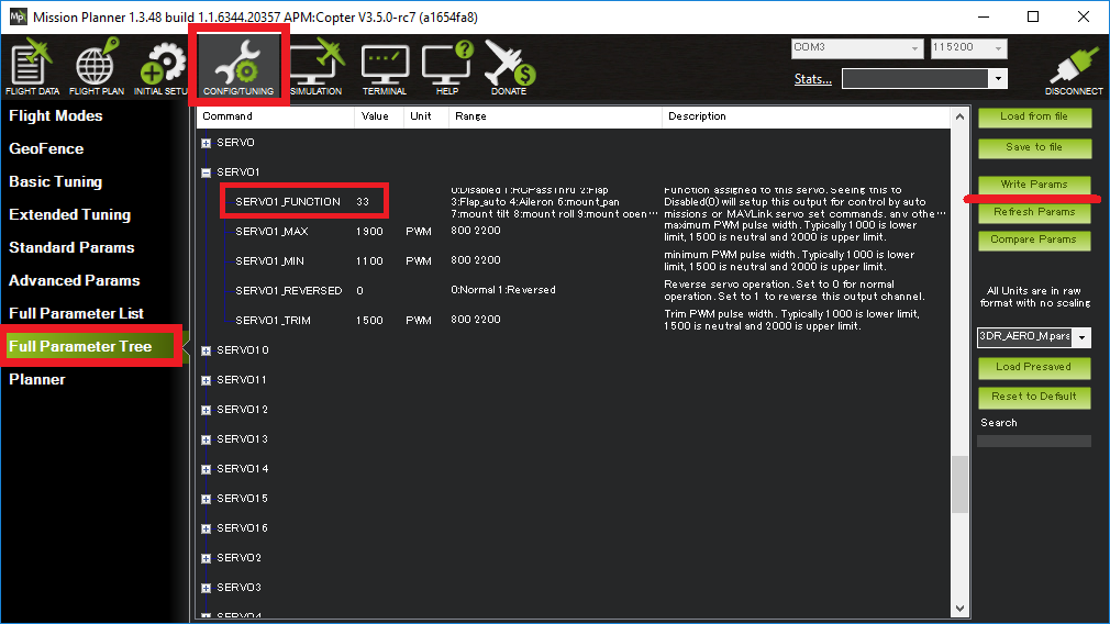
The SERVOn_FUNCTION parameters
In the advanced parameter view of your GCS you will find that each
SERVO output channel has a SERVOn_FUNCTION parameter. For example, SERVO5_FUNCTION controls the output function of channel 5, SERVO6_FUNCTION controls the output function of channel 6 and so on.
Not all the functions are available in each vehicle. Defaults are set to 0 when firmware for a vehicle type is first loaded. Choosing a frame configuration in Mission Planner during initial setup will set the outputs to the basic typical functions for that frame type. For example, fixed wing plane will set the first four outputs, SERVO1-SERVO4 to Aileron, Elevator, Throttle, and Rudder functions, respectively.
All of these functions may be used on multiple channels. So if you
want 3 elevator channels for some reason you can set SERVOn_FUNCTION
to 19 on 3 of your output channels.
Configuration
Configuration can be done using the SERVO tab of Mission Planner or by directly setting the SERVOx_FUNCTION parameter for an output.
For example, if you wished to re-order a Copter quad-x frame’s motors from the kitty-corner default to a more logical clockwise method, make these changes:
SERVO1_FUNCTION leave as 33 (aka “motor1”, front-right)
SERVO2_FUNCTION change from 34 (aka “motor2”, back-left) to 36 (motor #4, back-right)
SERVO3_FUNCTION change from 35 (aka “motor3”, front-left) to 34 (motor #2, back-left)
SERVO4_FUNCTION change from 36 (aka “motor4”, back-right) to 35 (motor #3, front-left)
GENERIC FUNCTIONS
Function |
ID |
Available in: |
GPIO |
-1 |
Plane, Copter, Rover, Sub |
Disabled |
0 |
Plane, Copter, Rover, Sub |
RCPassThru |
1 |
Plane, Copter, Rover, Sub |
RCPassThru1 |
51 |
Plane, Copter, Rover, Sub |
RCPassThru2 |
52 |
Plane, Copter, Rover, Sub |
RCPassThru3 |
53 |
Plane, Copter, Rover, Sub |
RCPassThru4 |
54 |
Plane, Copter, Rover, Sub |
RCPassThru5 |
55 |
Plane, Copter, Rover, Sub |
RCPassThru6 |
56 |
Plane, Copter, Rover, Sub |
RCPassThru7 |
57 |
Plane, Copter, Rover, Sub |
RCPassThru8 |
58 |
Plane, Copter, Rover, Sub |
RCPassThru9 |
59 |
Plane, Copter, Rover, Sub |
RCPassThru10 |
60 |
Plane, Copter, Rover, Sub |
RCPassThru11 |
61 |
Plane, Copter, Rover, Sub |
RCPassThru12 |
62 |
Plane, Copter, Rover, Sub |
RCPassThru13 |
63 |
Plane, Copter, Rover, Sub |
RCPassThru14 |
64 |
Plane, Copter, Rover, Sub |
RCPassThru15 |
65 |
Plane, Copter, Rover, Sub |
RCPassThru16 |
66 |
Plane, Copter, Rover, Sub |
RCIN1Scaled |
140 |
Plane, Copter, Rover |
RCIN2Scaled |
141 |
Plane, Copter, Rover |
RCIN3Scaled |
142 |
Plane, Copter, Rover |
RCIN4Scaled |
143 |
Plane, Copter, Rover |
RCIN5Scaled |
144 |
Plane, Copter, Rover |
RCIN6Scaled |
145 |
Plane, Copter, Rover |
RCIN7Scaled |
146 |
Plane, Copter, Rover |
RCIN8Scaled |
147 |
Plane, Copter, Rover |
RCIN9Scaled |
148 |
Plane, Copter, Rover |
RCIN10Scaled |
149 |
Plane, Copter, Rover |
RCIN11Scaled |
150 |
Plane, Copter, Rover |
RCIN12Scaled |
151 |
Plane, Copter, Rover |
RCIN13Scaled |
152 |
Plane, Copter, Rover |
RCIN14Scaled |
153 |
Plane, Copter, Rover |
RCIN15Scaled |
154 |
Plane, Copter, Rover |
RCIN16Scaled |
155 |
Plane, Copter, Rover |
Disabled
For normal operation, the Disabled output function sets the output value of the channel to 0, ie no PWM pulses being sent. The exception to this is when a MAVLink override of the channel or a mission servo set is used. So in some ways “disabled” could be called “mission-controlled”.
When you perform an auto mission you can ask for a servo to be set to a value as part of that mission. In that case you should set the SERVOn_FUNCTION for that channel to Disabled, so that the value doesn’t get changed by another output function immediately after the mission sets the value.
RCPassThru
Setting a channel to RCPassThru means it will output the value that is coming into the board from the corresponding input channel. For example, if SERVO5_FUNCTION is 1 (meaning RCPassThru) then channel 5 output will always be equal to channel 5 input.
Note
The servo output will exactly match the RC input source’s PWM value. RCx_TRIM/_MIN/_MAX and SERVOx_TRIM/_MIN/_MAX has no affect in this mode.
RCPassThru1 to RCPassThru16
This operates the same as RCPassThru explained above. However, instead of the SERVOx output being controlled by the RCx input, any RC input can be assigned to control this output. For example RCPassThru 1 (51) would assign RC Channel 1 input to control the output. So, for output 1, assigning 51 to the SERVO1_FUNCTION is identical to assigning the value of 1 passing RC Channel 1 to the output.
Note
normally passthru outputs will hold their last valid value during an RC failsafe. By setting the SERVO_RC_FS_MSK, selected passthru outputs can be set as if their input channel went to neutral. This is helpful for outputs controlling servo gimbals, or other manually controlled functions.
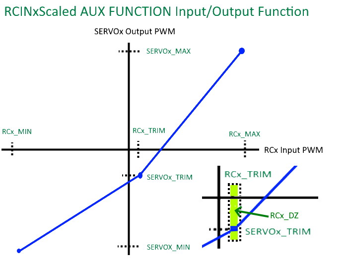
RCIN1Scaled to RCIN16Scaled
This operates similar to RCPassThru1 to RCPassThru16 above. However, instead of exactly passing the received PWM to the output, its is scaled.The RC input’s dead-zone(DZ) is also obeyed.
The upper PWM range from the input trim value to its maximum input is translated to its corresponding output’s trim to maximum parameter values range, and similarly for the ranges below the input’s trim value as shown below:
Note
the SERVOx_MIN/MAX values can be larger than what Mission Planner allows in some presentations. Use the CONFIG/Full Parameter Tree view to set parameters beyond their normal “safe” ranges.
Note
normally scaled passthru outputs will hold their last valid value during an RC failsafe. By setting the SERVO_RC_FS_MSK, selected passthru outputs can be set as if their input channel went to neutral. This is helpful for outputs controlling servo gimbals, or other manually controlled functions.
PLANE FUNCTIONS (Also applies to QuadPlanes)
Function |
ID |
Available in: |
Aileron |
4 |
Plane |
Elevator |
19 |
Plane |
Throttle |
70 |
Plane, Copter, Rover |
Throttle Left |
73 |
Plane, Copter, Rover |
Throttle Right |
74 |
Plane, Copter, Rover |
Rudder |
21 |
Plane |
Flap |
2 |
Plane |
Automatic Flaps |
3 |
Plane |
Flaperon Left |
24 |
Plane |
Flaperon Right |
25 |
Plane |
Elevon Left |
77 |
Plane |
Elevon Right |
78 |
Plane |
V-Tail Left |
79 |
Plane |
V-Tail Right |
80 |
Plane |
Differential Spoiler Left1 |
16 |
Plane |
Differential Spoiler Right1 |
17 |
Plane |
Differential Spoiler Left2 |
86 |
Plane |
Differential Spoiler Right2 |
87 |
Plane |
Ground Steering |
26 |
Plane, Rover |
Boost Engine Throttle |
81 |
Copter, QuadPlane |
Motor Enable Switch |
30 |
Copter, QuadPlane |
Landing Gear |
29 |
Copter, Plane |
AirBrakes |
110 |
Plane |
Throttle
Typical servo output for motor power control for vehicles. Multiple outputs can be used for multi-engine vehicles. Primary power control output for normal fixed-wing planes, single rotor helicopter, and rovers.
Throttle Left/ Right
In Plane, these outputs are for differential thrust in twin engine aircraft and the amount of yaw affecting the base throttle value is determined by RUDD_DT_GAIN. Also, in Plane’s vectored Tailsitters, these are the motor outputs. In Rover, these outputs are for control of the steering motors in Skid-Steering Rovers. In Copter, these outputs are used for the Bicopter motors.
Boost Engine Throttle
This output is for throttle control of an auxiliary Booster Motor to add an additional vertical thrust source in Multi-Copter and QuadPlane applications.
Motor Enable Switch
This provides an output that reflects the ARM/DISARM state of the vehicle to control a motor enable/kill switch. When ARMED, it is at SERVOx_MAX pwm, and at SERVOx_MIN pwm when disarmed.
Landing Gear
This output controls the landing gear servo(s) in Copter and Plane. See Landing Gear/ Retractable Camera Mount for more information.
COPTER / QUADPLANE FUNCTIONS
Function |
ID |
Available in: |
Motor 1 |
33 |
Copter, Sub, QuadPlane, HeliQuad, Traditional & Dual Heli |
Motor 2 |
34 |
Copter, Sub, QuadPlane, HeliQuad, Traditional & Dual Heli |
Motor 3 |
35 |
Copter, Sub, QuadPlane, HeliQuad, Traditional & Dual Heli |
Motor 4 |
36 |
Copter, Sub, QuadPlane, HeliQuad, Traditional & Dual Heli |
Motor 5 |
37 |
Copter, Sub, QuadPlane, Dual Helicopter |
Motor 6 |
38 |
Copter, Sub, QuadPlane, Dual Helicopter |
Motor 7 |
39 |
Copter, Sub, QuadPlane |
Motor 8 |
40 |
Copter, Sub, QuadPlane |
Motor 9 |
82 |
Copter, Sub |
Motor 10 |
83 |
Copter, Sub |
Motor 11 |
84 |
Copter, Sub |
Motor 12 |
85 |
Copter, Sub |
Motor Tilt |
41 |
QuadPlane |
Throttle Left |
73 |
Plane, Copter, Rover |
Throttle Right |
74 |
Plane, Copter, Rover |
Tilt Motor Left |
75 |
Copter, QuadPlane |
Tilt Motor Right |
76 |
Copter, QuadPlane |
Tilt Motor Rear |
45 |
QuadPlane |
Tilt Motor Rear Left |
46 |
QuadPlane |
Tilt Motor Rear Right |
47 |
QuadPlane |
Boost Engine Throttle |
81 |
Copter, QuadPlane |
Motor Enable Switch |
30 |
Copter, QuadPlane |
Parachute Release |
27 |
Copter |
Landing Gear |
29 |
Copter, Plane |
Winch |
88 |
Copter, Sub |
Rotor Head Speed |
31 |
Traditional & Dual Helicopter, HeliQuad |
Tail Rotor Speed |
32 |
Traditional Helicopter |
Motors 1 - 12
These are the Copter and QuadPlane VTOL motor outputs. For Multi-Copters, see Motor Order Diagrams. Or see Traditional Helicopter, or SingleCopter and CoaxCopter, or HeliQuads (Variable Pitch Multicopters).
Note
It is only possible to modify the output channel used, it is not possible to redefine the direction the motor spins with these parameters.
Throttle Left/ Right
In Copter, these outputs are used for the Bicopter motors.
Tilt Motor/ Tilt Motor Left/ Tilt Motor Right/ Tilt Motor Rear/ Tilt Motor Rear Left/ Tilt Motor Rear Right
These outputs control the tilt servos for Tilt Rotor Planes in Plane and Bicopters in Copter.
Boost Engine Throttle
This output is for throttle control of an auxiliary Booster Motor to add an additional vertical thrust source in Multi-Copter and QuadPlane applications.
Motor Enable Switch
This provides an output that reflects the ARM/DISARM state of the vehicle to control a motor enable/kill switch. When ARMED, it is at SERVOx_MAX pwm, and at SERVOx_MIN pwm when disarmed.
Parachute Release
See Parachute section.
Landing Gear
This output controls the landing gear servo(s) in Copter and Plane. See landing-gear for more information.
Winch
This output controls a winch for object delivery in Copter.
Rotor Head Speed
Motor control output for Traditional Helicopter.
Tail Rotor Speed
Output to Traditional Helicopter tail rotor ESC/Governor (future enhancement).
ROVER FUNCTIONS
Function |
ID |
Available in: |
Ground Steering |
26 |
Plane, Rover |
Throttle |
70 |
Plane, QuadPlane, Copter, Rover |
Throttle Left |
73 |
Plane, Copter, Rover |
Throttle Right |
74 |
Plane, Copter, Rover |
Main Sail Sheet |
89 |
Rover |
Throttle
Typical servo output for motor power control for vehicles. Multiple outputs can be used for multi-engine vehicles. Primary power control output for normal fixed-wing planes, single rotor helicopter, and rovers.
Throttle Left/ Right
In Plane, these outputs are for differential thrust in twin engine aircraft and the amount of yaw affecting the base throttle value is determined by RUDD_DT_GAIN. Also, in Plane’s vectored Tailsitters, these are the motor outputs. In Rover, these outputs are for control of the steering motors in Skid-Steering Rovers. In Copter, these outputs are used for the Bicopter motors.
ANTENNA TRACKER FUNCTIONS
Function |
ID |
Available in: |
Tracker Yaw |
71 |
Antenna Tracker |
Tracker Pitch |
72 |
Antenna Tracker |
Tracker Yaw/Pitch
These outputs control the pitch and yaw servos for an Antenna Tracker.
CAMERA/GIMBAL FUNCTIONS
Function |
ID |
Available in: |
Mount Yaw |
6 |
Plane, Copter, Rover, Sub |
Mount Pitch |
7 |
Plane, Copter, Rover, Sub |
Mount Roll |
8 |
Plane, Copter, Rover, Sub |
Mount Deploy/Retract |
9 |
Plane, Copter, Rover, Sub |
Camera Trigger |
10 |
Plane, Copter, Rover |
Mount2 Yaw |
12 |
Plane, Copter, Rover |
Mount2 Pitch |
13 |
Plane, Copter, Rover |
Mount2 Roll |
14 |
Plane, Copter, Rover |
Mount2 Deploy/Retract |
15 |
Plane, Copter, Rover |
Camera ISO |
90 |
Plane, Copter, Rover, Sub |
Camera Aperture |
91 |
Plane, Copter, Rover, Sub |
Camera Focus |
92 |
Plane, Copter, Rover, Sub |
Camera Shutter Speed |
93 |
Plane, Copter, Rover, Sub |
Mount Yaw/Pitch/Roll/Deploy
These control the output channels for controlling a servo gimbal. Please see the camera gimbal configuration documentation for details.
The Mount2 options are the same, but control a second camera gimbal.
Camera_trigger
The Camera_trigger output function is used to trigger a camera with a servo. See the camera gimbal documentation for details.
Camera ISO/Aperture/Focus/Shutter Speed
These outputs are used to remotely control the above values for BMMC (Blackmagic Micro Cinema Camera) compatible devices.
INTERNAL COMBUSTION ENGINE FUNCTIONS
Function |
ID |
Available in: |
Ignition |
67 |
Plane, Copter, Rover |
Choke |
68 |
reserved for future use |
Starter |
69 |
Plane, Copter, Rover |
Ignition/Starter/Choke
For control of an internal combustion engine’s spark plug/igniter, starter motor, and choke. See Internal Combustion Engines (ICE).
NEOPIXEL LED STRINGS
Neopixel LEDs/Strings can be controlled using Function IDs 120-123, thereby supporting up to four strings independently controlled. These may be used for ArduPilot notifications and warnings (See Notification Device Configuration) or controlled via LUA scripting (See Lua Scripts).
This is available in all vehicles.
ProfiLEDs
ProfiLEDs can be controlled using Function IDs 129-132, thereby supporting up to three strings independently controlled with a common clock. These may be used for ArduPilot notifications and warnings (See Notification Device Configuration) or controlled via LUA scripting (See Lua Scripts).
This is available in all vehicles.
MISCELLANEOUS FUNCTIONS
Function |
ID |
Available in: |
Gripper |
28 |
Plane, Copter, Rover, Sub |
EggDrop |
11 |
Deprecated |
Sprayer Pump |
22 |
Copter |
Sprayer Mixer |
23 |
Copter |
Output SERVOn_MIN PWM value |
134 |
Plane, Copter, Rover, Sub |
Output SERVOn_TRIM PWM value |
135 |
Plane, Copter, Rover, Sub |
Output SERVOn_MAX PWM value |
136 |
Plane, Copter, Rover, Sub |
Lights1 |
181 |
Sub |
Lights2 |
182 |
Sub |
Video Switch |
183 |
Sub |
Gripper
This is an output for controlling a servo or electromagnetic gripper for holding items for delivery applications. See Grippers (for delivery) for more information.
Sprayer Pump/Mixer
These outputs are controlling a Crop Sprayer.
Output SERVOn MAX/MIN/TRIM
Continuously outputs the parameter value set for that output. Used in button detection. See Buttons
GENERAL PURPOSE LUA SCRIPTING OUTPUTS
Lua Scripts can also directly control autopilot outputs. Using Function IDs 94-109 provides the ability to configure up to 16 of these outputs, if the autopilot is capable. This is available in all vehicles.
INTERNAL CONTROLLER ACCESS
Function |
ID |
Available in: |
RateRoll |
124 |
Copter |
RatePitch |
125 |
Copter |
RateThrust |
126 |
Copter |
RateYaw |
127 |
Copter |
These outputs provide the FeedForward terms fr om the attitude control loops, scaled by the ATC_RAT_x_FF PID parameter values for roll/pitch/yaw for use with external vehicle controllers.
DEFAULT VALUES
Either upon loading the firmware or selecting the frame type, certain default values will be set for the output functions. The user may move these to alternate servo/motor outputs if they desire. The default values are shown below:
VEHICLE TYPE SERVO |
1 |
2 |
3 |
4 |
5 |
6 |
7 |
8 |
9 |
10 |
11 |
12 |
MultiCopter |
33 |
34 |
35 |
36 |
37 |
38 |
39 |
40 |
82 |
83 |
84 |
85 |
Tricopter |
33 |
34 |
0 |
36 |
0 |
0 |
39 |
0 |
0 |
0 |
0 |
0 |
SingleCopter / CoAxialCopter |
33 |
34 |
35 |
36 |
37 |
38 |
0 |
0 |
0 |
0 |
0 |
0 |
Traditional Helicopter |
33 |
34 |
35 |
36 |
0 |
0 |
0 |
31 |
0 |
0 |
0 |
0 |
Dual Helicopter |
33 |
34 |
35 |
36 |
37 |
38 |
0 |
31 |
0 |
0 |
0 |
0 |
HeliQuad |
33 |
34 |
35 |
36 |
0 |
0 |
0 |
31 |
0 |
0 |
0 |
0 |
Fixed Wing Plane / Tailsitter |
4 |
19 |
21 |
70 |
0 |
0 |
0 |
0 |
0 |
0 |
0 |
0 |
QuadPlane |
4 |
19 |
21 |
70 |
33 |
34 |
35 |
36 |
0 |
0 |
0 |
0 |
QuadPlane Tricopter |
4 |
19 |
21 |
70 |
33 |
34 |
0 |
36 |
0 |
0 |
39 |
0 |
Rover |
26 |
0 |
70 |
0 |
0 |
0 |
0 |
0 |
0 |
0 |
0 |
0 |