Motor and Servo Configuration
This page describes the few parameters that should be set in order to support the steering and throttle method being used. This page is closely related to the Motor and Servo Connections page which describes the physical connections between the autopilot, motors, and servos.
Separate Steering and Throttle
For separate steering and throttle vehicles these parameters values should be set (they should already be set by default):
SERVO1_FUNCTION = 26 (GroundSteering)
SERVO3_FUNCTION = 70 (Throttle)
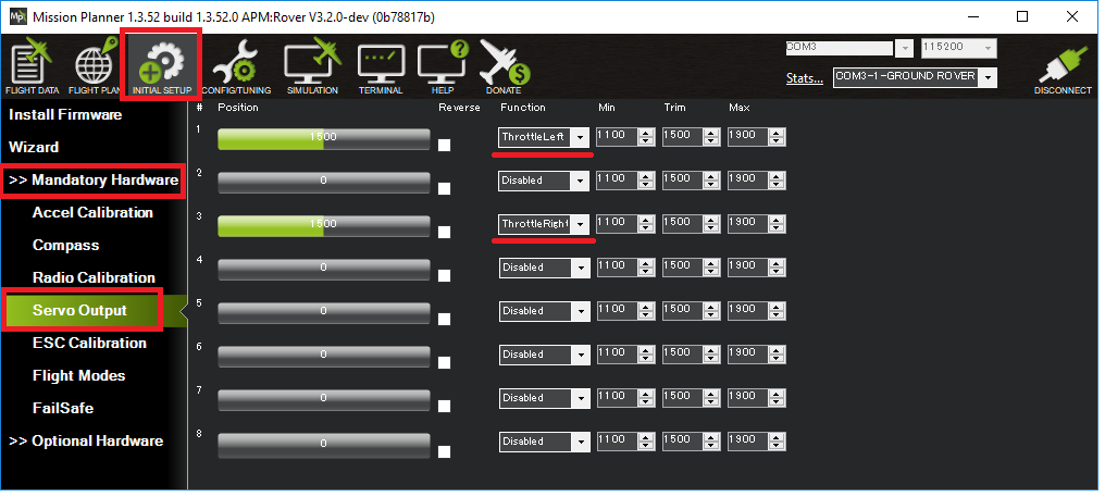
If using the mission planner, the Initial Setup >> Mandatory Hardware >> Servo Output page is a convenient way to do this

Skid Steering
For “Skid steering” vehicles (like R2D2) these parameters values will need to be set:
SERVO1_FUNCTION = 73 (Throttle Left)
SERVO3_FUNCTION = 74 (Throttle Right)
Omni Vehicles
For Omni vehicles (that can move left-to-right without changing heading) these parameter values will need to be set:
FRAME_TYPE = 1 (Omni3), 2 (OmniX) or 3 (OmniPlus)
SERVO1_FUNCTION = 33 (motor1)
SERVO2_FUNCTION = 34 (motor2)
SERVO3_FUNCTION = 35 (motor3)
SERVO4_FUNCTION = 36 (motor4)
Motor Driver Types
At least three different Motor Driver (aka ESC) types are supported which allows using ArduPilot with most motor drivers. The MOT_PWM_TYPE parameter should be used to ensure the output from the autopilot board matches the input required by the motor driver.
“Normal” is the most common and involves sending PWM values normally between 1000 and 2000 (1ms ~ 2ms) to an ESC. “OneShot and OneShot125” are variants of this (See PWM, OneShot and OneShot125 ESCs).
“DShotxxxx” is for use with DShot ESCs and uses a serial digital control stream (see DShot ESCs)
“Brushed With Relay” is for brushed motor drivers that use a relay pin to indicate whether it should rotate forward or backward. Output is 0-100% duty cycle waveform.
“Brushed BiPolar” is for brushed motor drivers that use basic PWM duty cycle to control motor direction and speed. These devices interpret a low duty cycle PWM value for full-speed reverse, 50% duty cycle as stopped, and a 100% duty cycle for full-speed forward. (Contrast to “Normal servo control PWM” where pulse width range 1-2ms is used for servo output position, and is only a ~5-10% duty-cycle overall.)
Note
Brushed motors are updated at the MOT_PWM_FREQ rate. Make sure that it is set at a value compatible with the brushed motor/esc you are using.
Reversing
Rover vehicles may/or may not use reversing motors depending on configuration. If an ESC is used, usually 1500us is used to indicate idle for PWM and DShot systems. Brushed drivers this point will be 50% duty cycle, if reversible, unless the BRUSHED_WITH_RELAY type is used.
Some ESCs need a brief pause at idle as they change direction. MOT_REV_DELAY can be used to provide that delay.
ESC Configuration
Some ESCs support three “Running Models”:
Forward with brake
Forward and reverse with brake
Forward and Reverse
For Rover to have full and straightforward control of the throttle it is best to set the “Running Model” to the 3rd option, “Forward and Reverse”. An ESC programming card compatible with the ESC can normally be used to change the ESC’s configuration.
Testing Motor direction
The Mission Planner (and perhaps other GCSs) can be used to test the direction of the motors:
plug in the vehicle’s battery and place the vehicle on a stand so that its wheels can move freely
connect with the Mission Planner using USB or telemetry radio
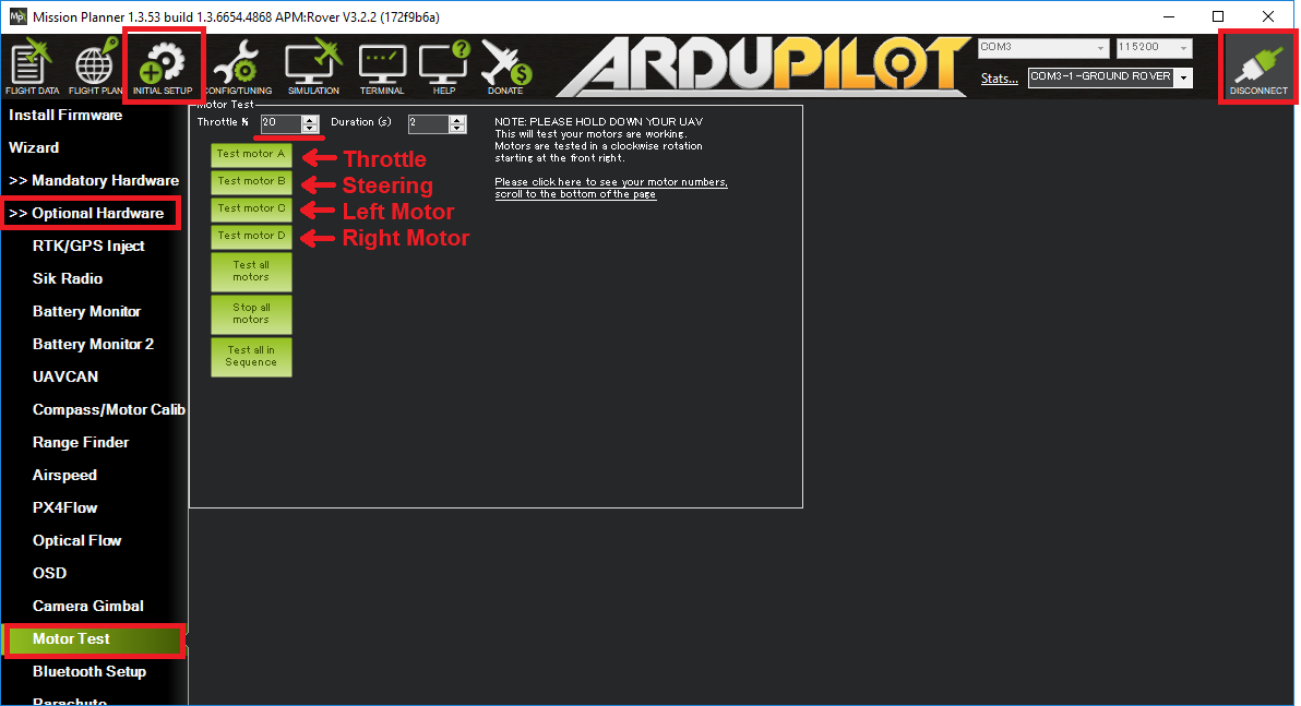
go to the Initial Setup >> Optional Hardware >> Motor Test page
increase the “Throttle %” to 20
push the “Test motor” buttons to test the steering and motors.
for rovers with separate steering and throttle, pushing the “Test motor A” button should cause the wheels to turn forward, “Test motor B” should cause steering to turn right.
for rovers with skid steering, “Test motor C” should cause the left wheel to turn forward. “Test motor D” should cause the right wheel to turn forward.
If the motors or steering do not move in the correct direction change the appropriate
SERVOx_REVERSEDvalue and try again.if a “command rejected” message appears or the motors or steering do not respond to the test, the cause may be written in the Mission Planner’s Flight Data >> Messages tab (see bottom left of the window). Common causes include the radio calibration having not been performed or the
SERVOx_FUNCTIONparameters having not been set correctly.
Minimum Throttle
Many motors and ESCs have a dead zone. This is the zone between the zero throttle value and the throttle value at which the motor starts to move. This can be compensated by setting minimum throttle in the firmware.
Tip
Remove wheels before proceeding with surface vehicles. Be aware of propellers on boats if they cannot be easily removed!
To fix the dead zone, open the motor test window in Mission Planner, as mentioned below. Find the minimum throttle value at which the motor turns on and set the parameter MOT_THR_MIN to that value. Now the motor should start at 1% throttle.
Steering Speed scaling
The amount of steering that a vehicle can apply without tipping due to lateral acceleration can be adjusted by changing MOT_SPD_SCA_BASE. Speeds below this value will have the full steering angle. Speeds above will have the maximum steering angle reduced by the fraction MOT_SPD_SCA_BASE / GroundSpeed.
This scaling is used at all times in Acro, Hold, Steering, Auto, RTL, Smart RTL, and Follow. In Guided mode, it is used except when direct steering and throttle are provided as input commands. In Manual mode, the use of this scaling is enabled by the first bit of MANUAL_OPTIONS.