EKF3 Affinity and Lane Switching
The EKF instantiates multiple instances of the filter called ‘lanes’. The “primary” lane is the one currently providing state estimates, other lanes are updated in the background and available for switching to.
Note
This page attempts to clarify an advanced configuration topic. The source code is the truth.
The number of possible lanes is the number of IMUs enabled for use (see EK3_IMU_MASK). Furthermore, the lanes are 1-1 bound to the (used) IMUs: lane 1 for IMU 1, lane 2 for IMU 2, etc.
Now, consider the other sensor types {Airspeed, Barometer, GPS, and Magnetometer (aka Compass)}. First, it is important to define the system’s notion of the “primary” sensor instance of each type. The primary sensor instance is the instance being actively relied upon. The initial primary sensor instance is selected by a user-modifiable parameter. The system may change which sensor instance is its primary, even in-flight, for example in case of a sensor fault. Thus “changing the primary instance” is one mechanism the system can use to switch which sensor instance is being relied upon.
A second mechanism for selecting which sensor instance to rely on is provided by “affinity” & lane-switching. Because modern-day vehicles may have redundant good quality sensors installed, affinity provides a way to force some EKF lanes to prefer sensor instances which are not the system-wide primary. If affinity for a sensor-type is disabled, each lane uses the system’s primary instance of the sensor. (Affinity being disabled is the conventional/default choice.) If affinity for a sensor-type is enabled, the sensor instances are distributed to lanes in a similar way as IMUs. Now with affinity enabled, lane-switching becomes a mechanism for sensor-switching. Each lane’s error score—used by the system to make a switching decision—takes into account innovations from all sensors used by that lane. Consider a noisy but not faulted sensor for which affinity is enabled: it makes the error-score for its lane bad. The system responds to the bad error score by lane-switching away from relying on it. Thus a mishap may be avoided by simply EKF lane-switching to a less-noisy IMU+sensor combination.
Example: Vehicle uses 4 IMUs, 2 Airspeeds, 3 Barometers, 2 GPS, and 3 Magnetometers. Affinity is disabled for airspeed & barometers, enabled for GPS & magnetometers.
| LANE | 1 | 2 | 3 | 4 |
|---|---|---|---|---|
| IMU | 1 | 2 | 3 | 4 |
| AIRSPEED | 1 | 1 | 1 | 1 |
| BAROMETER | 1 | 1 | 1 | 1 |
| GPS | 1 | 2 | 1 | 1 |
| MAGNETOMETER | 1 | 2 | 3 | 1 |
Numbers indicate the lane’s initial primary sensor instance.
Configuration Parameters
Note
Affinity is only available with EKF3, so make sure you are using it by ensuring EK3_ENABLE is set to “1” and AHRS_EKF_TYPE is set to “3”
The EK3_AFFINITY parameter is a bitmask which gives you the option to choose the sensors you want to enable affinity for. In every EKF lane, sensors for which affinity is not enabled will follow the system’s “primary” selection logic. For a sensor-type with affinity enabled, lane 1’s primary sensor is 1, lane 2’s primary sensor is 2, etc.
The EK3_ERR_THRESH parameter controls the sensitivity of lane switching. Lane errors are accumulated over time relative to the active primary lane. This threshold controls how much of an error difference between a non-primary and primary lane is required to consider the former performing better. Lowering this parameter makes lane switching more responsive to smaller ‘relative’ errors, and in practical you will see a more aggressive lane switching, and, vice-versa.
Warning
Misconfiguring the EK3_ERR_THRESH parameter could adversely affect the lane switching mechanism and have serious consequences which could lead to the loss of your vehicle. Please tune carefully.
Test Results
Following graphs are from SITL testing that show Affinity enabled lane changing when the primary lane’s sensor is subjected to noise/malfunctioning.
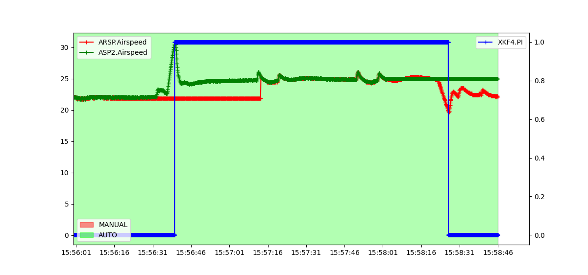
AIRSPEED
An example of lane switching for a plane with 2 airspeed sensors and airspeed affinity enabled. There are 2 IMUs, hence 2 active lanes. The primary lane’s airspeed sensor has failed to show changes in pressure, hence reporting a constant value. The speed of the plane is increased and a lane switch occurs. Similarly, the second airspeed sensor of the second lane (now the primary lane) is failed and the plane’s speed is decreased which again triggers a lane switch.
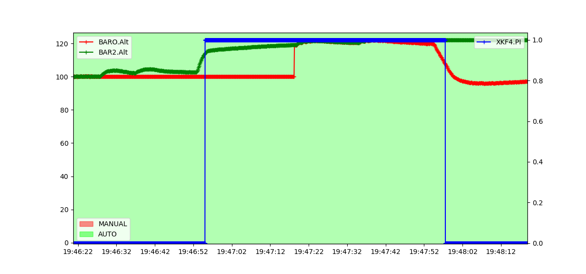
BAROMETER
An example of lane switching for a plane with 2 barometers and barometer affinity enabled. There are 2 IMUs, hence 2 active lanes. The primary lane’s barometer has failed to show changes in pressure, hence reporting a constant value. The altitude of the plane is increased and a lane switch occurs. Similarly, the second barometer of the second lane (now the primary lane) is failed and the plane’s altitude is decreased which again triggers a lane switch.
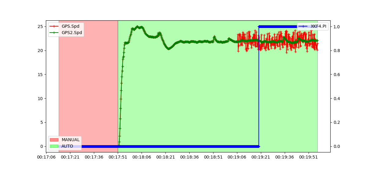
GPS
An example of lane switching for a plane with 2 GPS and GPS affinity enabled. There are 2 IMUs, hence 2 active lanes. The primary lane’s GPS is simulated with a random GPS Velocity Noise of range ±2m in all 3-axis. The actual speed can be tracked with the 2nd GPS. Subsequently, the EKF primary lane starts reporting a consistently high error and a lane switch occurs when the error crosses the set threshold.
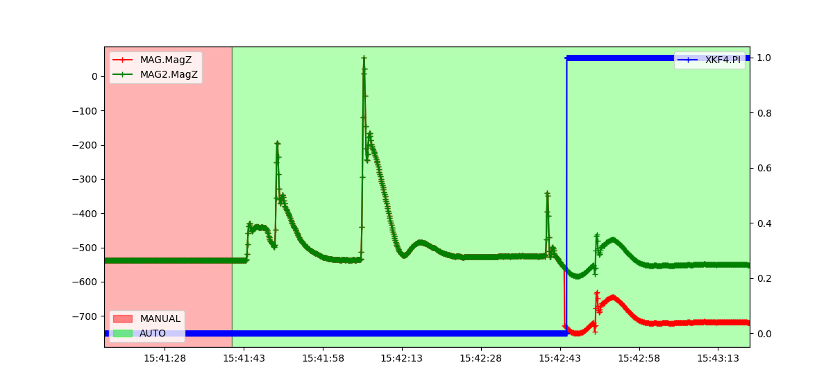
MAGNETOMETER
An example of lane switching for a plane with 2 Magnetometers and magnetometer affinity enabled. There are 2 IMUs, hence 2 active lanes. An error is simulated in the primary lane’s magnetometer by changing the offset of the z-axis while flying. The offset change can be tracked with the 2nd magnetometer. Subsequently, the EKF primary lane starts reporting a consistently high error and a lane switch occurs when the error crosses the set threshold.